

Flotation Cell for Flotation Plant Layout


Product Spotlights
Related Products
-
 Flotation Cell EPC Mining Project SupplierNegotiableMOQ: 1 Set
 -
Flotation Cell for Gravity Flotation PlantNegotiableMOQ: 1 Set
-
Flotation Cell for Gold Ore Concentration PlantNegotiableMOQ: 1 Set
-
Flotation Cell for Copper Ore Processing PlantNegotiableMOQ: 1 Set
-
Flotation Cell for Zinc Lead Flotation PlantNegotiableMOQ: 1 Set
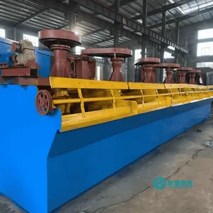
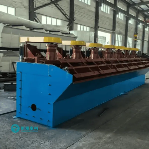
Product Introduction Flotation cell for flotation plant layout
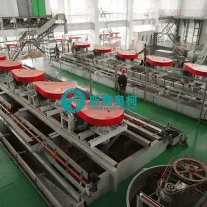
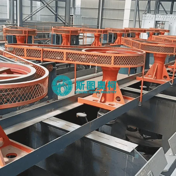
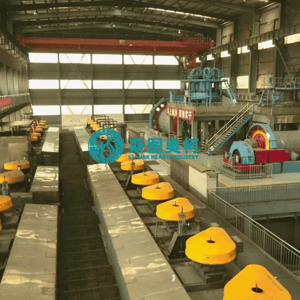
The flotation cell for flotation plant layout refers to the strategic arrangement and configuration of individual flotation machines within a processing facility. A well-designed layout optimizes the gravitational slurry flow, minimizes structural footprints, and ensures seamless connection between rougher, scavenger, and cleaner flotation stages to achieve maximum metallurgical recovery.
1.Application Flotation cell for flotation plant layout
The configuration of flotation cell layouts varies depending on the specific flowsheets of large-scale beneficiation plants. This layout design is vital for the following typical scenarios: Large-Scale Base Metal Plants: For processing massive volumes of copper, lead, or zinc ores. Large tank cells are arranged in linear cascades to handle high throughput with minimal piping complexity. Multi-Stage Cleaning Circuits: Used in precious metal or complex sulfide operations where multiple cleaning steps are required. The layout places cleaner cells at elevated positions or in stepped configurations to allow gravity-driven froth transport. Plant Modernization and Expansion: Tailored layouts designed to fit new high-volume flotation cells into existing mill buildings without disrupting current operations or exceeding structural weight limits.
2.Working Principle Flotation cell for flotation plant layout
The physical arrangement of flotation cells relies on fluid dynamics and material handling logic to process the mineral pulp efficiently. Hydraulic Gradient Flow: Flotation cells are typically arranged in a stepped or cascading configuration. The slurry flows from one cell to the next via gravity, reducing the need for intermediate slurry pumps and minimizing mechanical wear. Circuit Zoning: Cells are grouped into distinct zones: roughing (initial mass recovery), scavenging (recovering remaining middlings), and cleaning (upgrading the concentrate). The layout ensures that froth launders quickly direct the concentrate to the next appropriate stage. Accessibility and Maintenance: The layout incorporates centralized walkways, overhead crane access, and dedicated maintenance bays, allowing operators to service cell rotors, stators, and dart valves without halting the entire production line.
3.Advantages Flotation cell for flotation plant layout
Reduced Capital and Operating Costs: By maximizing gravity flow and minimizing the number of slurry pumps required between stages, the layout significantly lowers electricity consumption and pump maintenance expenses. Optimal Footprint Utilization: Compact, modular cell arrangements reduce the total structural steel and concrete foundation required for the mill building, lowering initial construction costs. Enhanced Process Control: A streamlined layout with clear sampling points and automated level-control gates allows operators to monitor froth depth and adjust air flow instantly, leading to more stable concentrate grades.
4.Technical Specifications
Category |
Model |
Effective Volume |
Capacity |
Impeller |
Impeller RPM Motor Power |
(kW)-Agitating |
Motor Power |
Single Weight (t) |
XJK type |
XJK-0.35 |
0.35 |
0.18-0.4 |
300 |
480 |
1.5 |
0.75 |
0.6 |
XJK-0.62 |
0.3-0.9 |
350 |
400 |
3 |
1.1 |
0.9 |
||
XJK-1.1 |
0.6-1.6 |
500 |
330 |
5.5 |
1.1 |
1.3 |
||
XJK-2.8 |
1.5-3.5 |
600 |
280 |
11 |
1.5 |
2.5 |
||
XJK-5.8 |
5.8 |
5-7 |
750 |
240 |
15 |
1.5 |
3.6 |
|
SF type Flotation |
SF-0.37 |
0.37 |
0.2-0.4 |
300 |
352-442 |
1.5 |
0.55 |
0.5 |
SF-0.65 |
0.65 |
0.3-1.0 |
350 |
336 |
3 |
1.1 |
1 |
|
SF-1.2 |
1.2 |
0.6-1.6 |
450 |
298 |
5.5 |
1.1 |
1.5 |
|
SF-2.8 |
2.8 |
1.5-3.5 |
550 |
268 |
11 |
1.5 |
2.3 |
|
SF-4 |
4 |
2-4 |
650 |
237 |
15 |
2.2 |
2.8 |
|
SF-8 |
8 |
4-8 |
760 |
191 |
30 |
2.2 |
4.3 |
|
SF-10 |
10 |
5-10 |
760 |
191 |
30 |
3 |
4.6 |
|
SF-16 |
16 |
6-16 |
850 |
180 |
45 |
3 |
7.8 |
|
SF-20 |
20 |
8-20 |
730 |
186 |
55 |
3 |
9.8 |
|
| JJF type Flotation machine | JJF-2 |
2 |
1-3 |
370 |
400 |
11 |
1.1 |
1.9 |
JJF-4 |
4 |
2-4 |
410 |
305 |
15 |
1.5 |
2.3 |
|
JJF-8 |
8 |
4-8 |
540 |
233 |
22 |
2.2 |
4.5 |
|
JJF-10 |
10 |
5-10 |
540 |
233 |
22 |
2.2 |
4.9 |
|
JJF-16 |
16 |
5-16 |
700 |
180 |
37 |
2.2 |
8.2 |
|
JJF-20 |
20 |
5-20 |
730 |
180 |
37 |
2.2 |
10.5 |

Send Inquiry to This Supplier


You May Also Like
-
36、flotation Cell for Refractory Gold OreNegotiableMOQ: 1 Set
-
Flotation Cell for Complex Ore BeneficiationNegotiableMOQ: 1 Set
-
Flotation Cell for Low Grade Ore UpgradeNegotiableMOQ: 1 Set
-
Flotation Cell for Mining Plant OptimizationNegotiableMOQ: 1 Set
-
Flotation Cell for Metallurgical PlantNegotiableMOQ: 1 Set
-
Flotation Cell for Mineral Processing EngineeringNegotiableMOQ: 1 Set
-
Flotation Cell for Mining Plant ExpansionNegotiableMOQ: 1 Set
-
Flotation Cell for South America Mining ProjectsNegotiableMOQ: 1 Set
-
Flotation Cell for Bolivia Mining PlantNegotiableMOQ: 1 Set
-
Flotation Cell for Peru Mining ProjectsNegotiableMOQ: 1 Set


