

GE IS200TPROH1BBB TPRO Series Protection Terminal Blocks

Related Products
-
 GE SR745-W2-P5-G5-HI 745 Series Transformer Monitoring RelaysNegotiableMOQ: 1 Piece
 -
GE IC698CRE030 Redundant CPU ModuleNegotiableMOQ: 1 Piece
-
GE IC698CMX016-ED Controls the Memory Swap ModuleNegotiableMOQ: 1 Piece
-
GE IC698PSA100 Power ModuleNegotiableMOQ: 1 Piece
-
GE 369-HI-0-M-0-0-0 Motor Protection RelayNegotiableMOQ: 1 Piece
1. Product Description
Model: IS200TPROH1BBB
Version: Standard Edition
Global Part Number: IS200TPROH1BBB
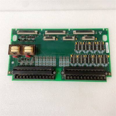
Product Series: GE Speedtronic Mark VI TPRO Series Protection Termination Board (Emergency Overspeed & Synchronization Protection, compatible with thermal, gas turbine, combined cycle power plants)
Product Category: Industrial-grade high-reliability protection termination/interface board (integrated EOS signal conditioning, trip solenoid driving, backup synchronization check, surge suppression, terminal distribution, isolation, fault diagnosis)
Country of Origin: USA
Core Functions
The IS200TPROH1BBB is a dedicated TPRO protection termination board designed by GE Vernova for the Mark VI Speedtronic turbine control system. Unlike general I/O modules, its core advantage lies in an emergency overspeed (EOS) and synchronization protection link independent of the main controller, which works with the VPRO protection board to form a triple redundant turbine safety system, directly driving trip solenoids and providing isolated transmission of critical signals.It adopts industrial-grade high-reliability components and conformal coating, standard with 2 sets of 48-channel high-density terminal blocks, 2 dedicated protection relays, MOV surge suppressors, 3 adjustable potentiometers; 2500V AC reinforced electrical isolation, supporting 125VDC trip circuits, speed/temperature/generator voltage/bus voltage signal acquisition; built-in fixed+configurable filtering (0.5–10ms), digital response ≤1ms, relay output response ≤7ms; can control up to 3 groups of trip solenoids connected by TREx/TRPx terminal blocks; communication compatible with GE proprietary backplane bus, Modbus RTU, seamlessly linking with Mark VI controllers, VPRO protection modules, HMIs, plug-and-play without additional drivers.Front-mounted LED diagnostic array and graded alarm, real-time monitoring of terminal status, relay contacts, power health, communication links, trip circuits; supports three-level authority management (Administrator/Operator/Read-only), generating complete operation/fault/trip event logs; dual redundant 24VDC (±10%) + 125VDC trip power input, enhanced EMI/EMC design, compliant with IEC 61000-6-2 standards, resistant to strong electromagnetic interference, dust and temperature fluctuations in power plants, ensuring millisecond-level execution of overspeed protection and trip commands.
Application Scenarios
Widely used in gas turbines, steam turbines, combined cycle power plants, distributed energy stations and other energy scenarios requiring high turbine safety, overspeed protection, and synchronous grid connection, especially suitable for thermal power/gas turbine projects with Mark VI+VPRO triple redundant protection architecture.Specific scenarios include: emergency overspeed protection and trip control of main steam turbines in power plants; synchronous check and backup protection during gas turbine startup/shutdown; turbine safety interlocking of multi-unit combined cycle systems; can be seamlessly integrated with GE CIMPLICITY HMI/SCADA, historians, HART smart instruments, safety PLCs, deployed in turbine control cabinets, working in conjunction with VPRO through high-speed backplanes to achieve integrated safety control of rapid trip for excessive speed, grid-connected synchronous check, graded fault alarm, and real-time monitoring of trip circuit status.
2. Specifications
| Parameter Category | Details |
|---|---|
| Software Specifications | Supported protocols: GE proprietary backplane bus, Modbus RTU; Functions: emergency overspeed protection (EOS) signal forwarding, backup synchronization check, trip solenoid driving (up to 3 groups), surge protection, adjustable filtering 0.5–10ms, three-level authority, complete event/fault/operation logs; Compatibility: seamless adaptation to Mark VI controllers, VPRO protection boards, supporting CIMPLICITY, GE Control System Toolbox; Diagnostics: terminal/relay/power/communication abnormal alarms, LED locates fault points and outputs error codes |
| Hardware Requirements | Compatible racks: Mark VI 13/21-slot standard control racks; Interfaces: 2×48-channel high-density terminal blocks, GE proprietary backplane interface, 2500V AC isolation, USB local configuration port, 125VDC trip circuit terminals; Installation: rack-mounted, fits 19-inch industrial control cabinets, weight approx. 0.6kg, protection class IP20 (card level) |
| Environmental Adaptability | Operating temperature: -30℃~+65℃; Storage temperature: -40℃~+85℃; Relative humidity: 5%~95% (non-condensing); Immunity: IEC 61000-6-2, built-in MOV surge suppressor, dual-stage EMI filter; MTBF≥15000 hours, dual redundant power input, with CE, UL, RoHS certification, resistant to mechanical vibration and shock |
3. Installation and Maintenance Guide
Pre-installation Requirements
Environment: Must be installed in a dust-free, non-condensing, well-ventilated Mark VI standard cabinet, strictly prohibited near inverter power modules and high-voltage busbars; temperature -30℃~+65℃, humidity 5%–95% non-condensing; configure online UPS to ensure dual redundant 24VDC power + 125VDC trip power, strictly prohibited deployment with programming computers in the same cabinet to reduce interference risks.
System Preparation: Pre-install the corresponding version of GE Control System Toolbox; open necessary communication ports; configure TPRO and VPRO linkage parameters, trip thresholds, filtering values in advance, and test backplane communication and trip circuit connectivity.
Installation Procedure: Fix on the rack rail, ensure the backplane interface is fully inserted; connect dual redundant 24VDC (reverse polarity strictly prohibited!), 125VDC trip power, speed/voltage signal lines, trip solenoid lines; run Toolbox to complete firmware identification and parameter download, paths without spaces/Chinese characters; select "Keep configuration" during upgrades, confirm all LEDs are green, no alarms, and trip circuit test is normal after restart.
Parameter Configuration: Set communication address and backplane rate; configure speed/voltage signal range and filtering values; set trip thresholds, synchronization check parameters, relay action delay; configure three-level permissions; test overspeed simulation trip, synchronization signal check, communication links, log functions; specify log storage path and enable diagnostics.
Routine Inspection Points
Operating Status: Check LED indicators (green for normal power/communication/protection, red for alarm/trip), no abnormal overheating on the module surface (≤45℃); confirm speed and voltage data are consistent with the field through CIMPLICITY, no sticking alarms in the trip circuit, and normal VPRO linkage.
Log Inspection: Export logs regularly, filter and handle overspeed events, trip actions, communication packet loss, permission changes, relay abnormal records in a timely manner; clean up expired logs to avoid storage overflow.
Network and Environment: Check terminal blocks, backplane connections, power lines for looseness; cabinet temperature and humidity meet requirements; UPS and redundant power supplies operate normally; recheck grounding resistance
Parameter Verification: Confirm model and part number (IS200TPROH1BBB); no abnormal modifications to trip thresholds, filtering, synchronization parameters; test the reliability of simulated overspeed trip and relay action.
Periodic Maintenance
Monthly: Remove dust from the module and cabinet (focus on cleaning terminal blocks and backplane interfaces); back up protection configurations and trip circuit parameters; check power and communication interfaces for looseness; test LED diagnostics and alarm functions.
Quarterly: Check CPU, memory, disk usage of the control station; update system and Toolbox patches; recheck permissions; fine-tune filtering parameters according to season/load; troubleshoot potential hardware risks and implement GE official safety recommendations.
Semi-annually: Perform full backup of configurations and historical logs; verify module firmware integrity; validate and install GE official patches in a test environment; restart to release resources; check electrical isolation performance, redundant power switching, trip circuit on-off; evaluate module health, perform preventive replacement if necessary.
4. Common Faults and Troubleshooting
| Fault Symptom | Possible Causes | Troubleshooting & Solutions |
|---|---|---|
| Module fails to start, initialization error | Missing driver/configuration components; incompatible version; corrupted configuration file; poor backplane contact | Install the complete Control System Toolbox; confirm version compatibility with Mark VI/VPRO; import backup configuration; reinsert the module and fasten the backplane interface |
| Unable to communicate with VPRO/Mark VI controller | Incorrect address/rate configuration; backplane bus failure; damaged communication module | Verify communication parameters and test connectivity; check backplane cables and slots; replace with a spare communication module |
| Abnormal speed signal/overspeed protection refusal to act | Incorrect wiring/loose terminals; unreasonable filtering; incorrect threshold settings; faulty sensor/VPRO | Recheck and tighten wiring; adjust filtering to 1–3ms; verify trip thresholds; check speed sensors and VPRO modules |
| Abnormal relay output/trip circuit | Overloaded load; aging relay; abnormal 125VDC power; short circuit in the loop | Verify the load is within the rated range; replace the faulty relay; check 125VDC trip power; troubleshoot the short circuit in the output loop and repair |
| Frequent module restart/power alarm | Voltage fluctuation beyond 24VDC±10%/abnormal 125VDC; poor grounding; excessive EMI interference; faulty power module | Check UPS and redundant power supply; repair grounding resistance |

Send Inquiry to This Supplier


You May Also Like
-
GE 369-HI-R-0-0-E-0-E Motor Management RelayNegotiableMOQ: 1 Piece
-
GE 151X1235BC01SA01 10-slot Ethernet SwitchNegotiableMOQ: 1 Piece
-
GE 369-LO-0-M-F-E-0-0 Digital RelayNegotiableMOQ: 1 Piece
-
GE SR469 Series Motor Management RelayNegotiableMOQ: 1 Piece
-
GE F650BABF2G0LOSHE Multi-functional Digital ControllerNegotiableMOQ: 1 Piece
-
GE F650-G-N-A-B-F-2-G-1-HI-C-E Comprehensive Protection DeviceNegotiableMOQ: 1 Piece
-
GE IC697PCM711 Single-slot Programmable Coprocessor ModuleNegotiableMOQ: 1 Piece
-
GE IC697MDL750 Discrete Output ModuleNegotiableMOQ: 1 Piece
-
GE VME-5565 Reflective Memory VME Node CardNegotiableMOQ: 1 Piece
-
GE VME-7807RC High-performance Single-board ComputerNegotiableMOQ: 1 Piece


