

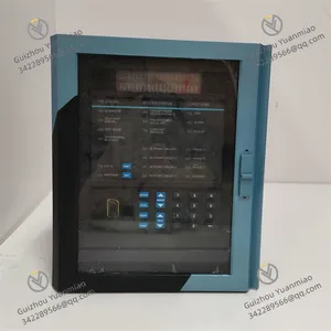
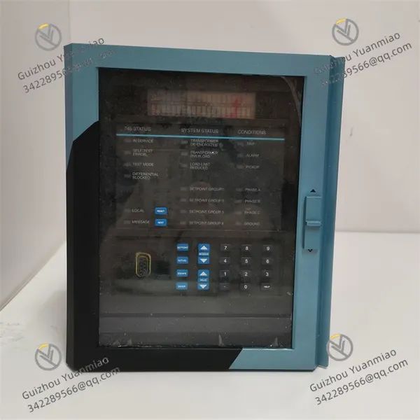
GE SR745-W2-P5-G5-HI 745 Series Transformer Monitoring Relays
Related Products
-
 GE IC697PWR724 90-70 Series PLC Power Supply ModulesNegotiableMOQ: 1 Piece
 -
GE IC800SSI228RD2-CE SSI Signal Input ModuleNegotiableMOQ: 1 Piece
-
GE IS200TBCIH2CCD Group-isolated Dry Contact Input Terminal BlockNegotiableMOQ: 1 Piece
-
GE IS200TRLYH1B Relay Output Terminal BoardNegotiableMOQ: 1 Piece
-
GE IS200TCATH1ABA Simulation Terminal BoardNegotiableMOQ: 1 Piece
1. Product Description
- Model: SR745-W2-P5-G5-HI
- Version: Standard Edition (Industrial-grade Full-function Edition)
- Global Part Number: SR745-W2-P5-G5-HI (GE Original Part Number, compatible with Multilin 745 Series Transformer Protection System)
- Product Series: GE Multilin 745 Series Transformer Management Relay (Dedicated for two-winding/three-winding transformers, integrating protection, monitoring and control functions)
- Product Category: Industrial-grade high-performance transformer protection and management relay (built-in multi-processor, integrating percent differential protection, overcurrent protection, overexcitation protection, with harmonic monitoring, waveform capture and adaptive restraint functions, providing comprehensive safety protection for various power transformers)
- Country of Origin: USA
Core Functions
The SR745-W2-P5-G5-HI is a high-performance integrated protective relay designed by GE Vernova's Multilin series specifically for small, medium and large power transformers. Unlike general protection modules, its core advantage lies in **integrated transformer protection and management integration, which can realize full-life cycle protection, monitoring and control of transformers without additional components. Equipped with a multi-processor architecture, it can flexibly adapt to the protection needs of two-winding or three-winding transformers, effectively solving the problem of false tripping caused by inrush current and ensuring the safe and stable operation of transformers.
It adopts industrial-grade high-reliability electronic components and protective design, standard with multi-channel current input (two windings per phase, 5A rated input), 7 analog outputs, integrating core functions such as percent differential protection, overcurrent protection, overexcitation protection, underfrequency protection and frequency rate-of-change protection; it has adaptive harmonic restraint technology, which can accurately monitor individual harmonics and total harmonic distortion (THD), automatically adjust the pickup settings of overcurrent elements, and avoid false actions caused by inrush current[2][7]; built-in waveform capture function, which can record waveform data under fault, inrush current or alarm conditions, support digital format export and playback, facilitating fault tracing; equipped with a 40-character LCD display, status indicators and operation keyboard, supporting RS232 programming port, parameters can be configured through EnerVista setup software, with convenient operation.
Communication is compatible with mainstream industrial protocols such as Modbus TCP/RTU and IEC 61850, which can be seamlessly linked with GE CIMPLICITY HMI/SCADA, historians and power monitoring systems, plug-and-play; supports multiple setpoint groups, which can flexibly switch protection parameters according to different power system configurations, has autoconfiguration function, all current transformers (CTs) are connected in wye, no special wiring required[2][7]; control power supply supports 90-300VDC, 70-265VAC (48-62Hz) wide voltage input, enhanced EMI/EMC design, compliant with IEC 61000-6-2 industrial standards, resistant to strong electromagnetic interference and voltage fluctuations in power systems, adapting to various industrial on-site environments, and also has loss of life protection function to extend equipment service life.
Application Scenarios
Widely used in power, energy, industrial manufacturing and other fields, it is specially designed for the protection and management of small, medium and large power transformers, especially suitable for industries with high requirements for power supply reliability and stability, such as metallurgy, oil and gas, petrochemical, chemical industry, papermaking and printing, textile printing and dyeing, machinery manufacturing, electronic manufacturing and automobile manufacturing.
Specific scenarios include: protection and monitoring of power transformers in factory power distribution systems, safety protection of power grid supporting transformers, management of supporting transformers in new energy power stations (photovoltaic/wind power), protection of centralized power supply transformers in industrial parks; it can be seamlessly integrated with GE power monitoring systems, third-party PLCs and intelligent instruments, deployed in power distribution control cabinets, realizing integrated functions of transformer differential protection, overcurrent/overexcitation alarm, harmonic monitoring, fault waveform capture, remote control and parameter debugging, meeting the high availability requirements for 24/7 continuous operation (availability above 99.99%), and adapting to the protection needs of different specifications of power transformers.
2. Specifications
Parameter Category |
Details |
|---|---|
Software Specifications |
Supported protocols: Modbus TCP/RTU, IEC 61850;Functions: percent differential protection, overcurrent protection, overexcitation protection, underfrequency protection, frequency rate-of-change protection, adaptive harmonic restraint, individual harmonic and THD monitoring, waveform capture and playback, multiple setpoint groups, autoconfiguration function, loss of life protection, three-level authority management (Administrator/Operator/Read-only), complete export of fault/operation/waveform logs;Compatibility: compatible with EnerVista setup software, CIMPLICITY HMI/SCADA, supporting various power monitoring systems;Diagnostics: currentvoltage abnormality, excessive harmonics, overexcitation, communication interruption alarm, LCD display and indicators locate fault points and output error codes. |
Hardware Requirements |
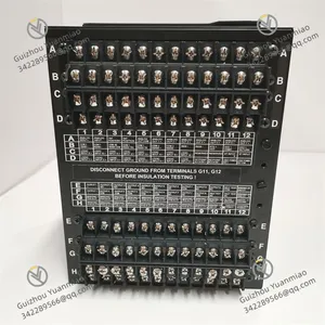
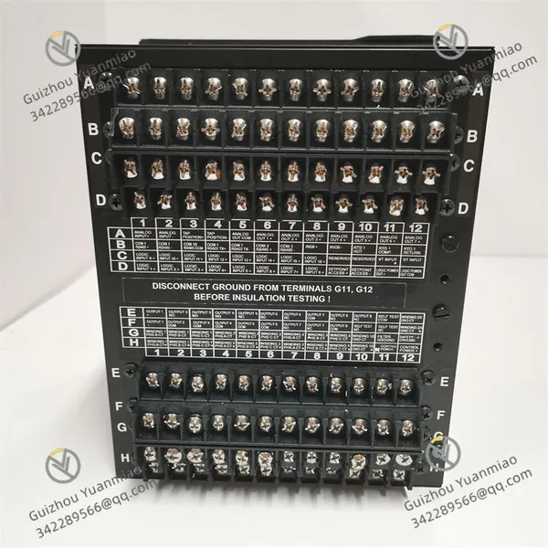
Compatible equipment: small, medium and large two-winding/three-winding power transformers;Interfaces: multi-channel current input (two windings per phase, 5A rated input), 7 analog outputs, RS232 programming port, Ethernet port, standard terminal blocks;Installation: DIN rail mounting or panel mounting, draw-out relay design, fits standard 19-inch industrial control cabinets, weight approx. 0.8kg, protection class IP20 (relay body). |
Environmental Adaptability |
Operating temperature: -30℃~+65℃;Storage temperature: -40℃~+80℃;Relative humidity: 5%~95% (non-condensing);Altitude: ≤2000m;Immunity: compliant with IEC 61000-6-2 industrial EMC standards, built-in anti-interference circuit;MTBF≥15000 hours, wide voltage control power supply (90-300VDC, 70-265VAC 48-62Hz), with CE, UL, RoHS certification, resistant to mechanical vibration and shock, avoiding high-concentration corrosive gas environment. |
3. Installation and Maintenance Guide
Pre-installation Requirements
- Environment: Must be installed in a dust-free, non-condensing, well-ventilated power distribution control cabinet, strictly prohibited near strong interference sources such as inverter power modules and high-voltage busbars; temperature -30℃~+65℃, humidity 5%–95% non-condensing, avoiding high-concentration corrosive gas environment, ensuring unobstructed ventilation ports for heat dissipation[3][5]; configure online UPS to ensure stable power supply of control power, strictly prohibited deployment with programming computers in the same cabinet to reduce interference risks.
- System Preparation: The control station is pre-installed with EnerVista setup software, and necessary communication ports are opened; confirm that current transformers (CTs) are connected in wye in advance, configure protection settings, harmonic monitoring parameters and communication parameters, test the connectivity with power monitoring system and transformer, and ensure that wiring complies with electrical specifications and safety standards.
- Installation Procedure: Fix with DIN rail or panel, ensure firm installation and good ventilation, avoid excessive stacking; connect current input lines, analog output lines, control power lines and communication lines (strictly follow the wiring diagram, strictly prohibited reverse connection or wrong connection!); run EnerVista software to complete firmware identification and parameter download, paths without spaces/Chinese characters; always select "Keep configuration" during upgrades, after restart, confirm that the LCD display is normal, all indicators are green, no alarms, and complete waveform capture and protection function tests.
- Parameter Configuration: Set communication address, protocol type and current input range; configure protection settings (differential, overcurrent, overexcitation, etc.), harmonic monitoring thresholds and setpoint group parameters; configure waveform capture trigger conditions and log storage path; set three-level permissions; test protection functions, harmonic monitoring, waveform playback and communication links to ensure all functions are normal.
Routine Inspection Points
- Operating Status: Check that the LCD display is normal, indicator status (green for normal power/communication/protection, red for alarm), no abnormal overheating on the relay body (≤45℃); confirm that current, voltage and harmonic data are consistent with the field through EnerVista software or HMI, protection functions are normally enabled, no false alarms or false tripping.
- Log Inspection: Export fault logs, operation logs and waveform data regularly, filter records of excessive harmonics, overexcitation, communication abnormalities and protection actions, and analyze and handle them in a timely manner; clean up expired logs and waveform data to avoid storage overflow, ensuring the completeness and traceability of logs.
- Network and Environment: Check that terminal blocks, communication interfaces and power lines are free of looseness and oxidation; cabinet temperature, humidity and ventilation meet requirements; UPS and control power supply operate normally, and voltage fluctuation is within the rated range (90-300VDC, 70-265VAC); recheck grounding resistance
- Parameter Verification: Confirm model and part number (SR745-W2-P5-G5-HI); no abnormal modifications to protection settings, harmonic monitoring parameters and communication parameters; test the reliability of protection actions, waveform capture function and communication link stability.
Periodic Maintenance
- Monthly: Remove dust from the relay body and cabinet (focus on cleaning terminal blocks, communication interfaces and ventilation ports); back up protection configurations, setpoint group parameters and historical waveform data; check power and communication interfaces for looseness; test indicators, LCD display and alarm functions to confirm normal operation.
- Quarterly: Check the operation status of control station software, update EnerVista software and relay firmware (follow GE official guidelines); recheck authority management; fine-tune protection settings and harmonic monitoring thresholds according to power grid load changes; troubleshoot potential hardware risks, implement GE official safety recommendations, and calibrate measurement accuracy.
-Semi-annually: Perform full backup of configurations, logs and waveform data; check the electrical performance of the relay and the contact status of terminal blocks; test the reliability of protection function linkage, waveform capture and playback functions; evaluate the operation health of the relay, check insulation performance, and perform preventive replacement if necessary.
4. Common Faults and Troubleshooting
Fault Symptom |
Possible Causes |
Troubleshooting & Solutions |
|---|---|---|
Relay fails to start, LCD no display |
Control power not connected/voltage abnormal; loose/wrong wiring; firmware damage; faulty power module |
Check control power supply (90-300VDC, 70-265VAC) to ensure stable voltage; recheck and tighten terminals, correct reverse wiring; import backup firmware or reflash; replace with the same model power module. |
Unable to communicate with monitoring system/programming software |
Incorrect communication address/protocol configuration; faulty communication cable; port blocked by firewall; damaged RS232/Ethernet interface |
Verify and reconfigure communication parameters; replace communication cable and test connectivity; open corresponding communication ports; check interface wiring, replace with spare communication interface or repair the relay. |
Abnormal harmonic monitoring/false protection action |
Incorrect CT wiring; unreasonable harmonic monitoring threshold settings; adaptive restraint function not enabled; inrush current interference |
Confirm that CTs are connected in wye and recheck wiring; adjust harmonic monitoring thresholds to a reasonable range; enable adaptive harmonic restraint function; optimize protection settings to avoid false triggering by inrush current. |
Waveform capture failure/unable to playback |
Incorrect trigger condition settings; insufficient storage capacity; outdated firmware version; incorrect operation steps |
Reconfigure waveform capture trigger conditions (fault, inrush current, etc.); clean up expired waveform data to free up storage; upgrade relay firmware and EnerVista software; re-execute waveform capture and playback operations according to the operation manual. |
Frequent relay alarms/protection refusal to act |
Incorrect protection setting configuration; abnormal current/voltage signals; faulty sensor (CT); damaged internal components of the relay |
Verify and reconfigure protection settings; check current/voltage signals and troubleshoot line faults; test CT performance and replace faulty CT; if internal components are damaged, replace with the same model SR745-W2-P5-G5-HI relay. |

Send Inquiry to This Supplier


You May Also Like
-
GE IS420ESWAH2A Unmanaged Ethernet / IONet SwitchesNegotiableMOQ: 1 Piece
-
GE IS200AEPGG1AAA Drive Control ModuleNegotiableMOQ: 1 Piece
-
GE DS6800CCIE1F1D Digital Input/Output (I/O) ModulesNegotiableMOQ: 1 Piece
-
GE IS200TVIBH2BBB Vibration Terminal Board (TVIB)NegotiableMOQ: 1 Piece
-
GE IS200EPMCH1 EPMC Card, PCI Mezzanine CardNegotiableMOQ: 1 Piece
-
GE 531X304IBDAMG1 Isolated Terminal Block for Contact Input GroupsNegotiableMOQ: 1 Piece
-
GE DS200IQXSG1AAA Inverter Snubber Board,IQXSNegotiableMOQ: 1 Piece
-
GE IS215WEMAH1A WEMA and BPPS BoardNegotiableMOQ: 1 Piece
-
GE DS200LDCCH1AKA Drive Control/LAN Communication BoardNegotiableMOQ: 1 Piece
-
GE IS410TRLYS1B Base Plate Turbine Specific Primary Trip BoardNegotiableMOQ: 1 Piece


