Home > Electrical & Electronics > Electrical Control System > SCHNEIDER 140DDI35310 Discrete Input Module

SCHNEIDER 140DDI35310 Discrete Input Module

SCHNEIDER 140DDI35310 Discrete Input Module photo-1
Negotiable MOQ: 1 Piece (Price negotiable depending on order volume and customization)
Key Specifications
Get Latest Price
Material:
Other, Global universal model
Condition:
Other, Global universal model
Task:
Other, Global universal model
Payment & Shipping
Payment Methods:
Port of Shipment:
guizhou
Delivery Detail:
Delivery time depends on order quantity.
Material Other, Global universal model
Condition Other, Global universal model
Task Other, Global universal model
Mathematical Model Other, Global universal model
Signal Other, Global universal model
Customized Non-Customized
Structure Other, Global universal model
Operating Temperature -25℃-70℃
Relative Humidity 5%-95% (non-condensing)
Dimensions 100mm×140mm×210mm

I. Overview


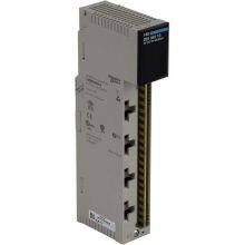
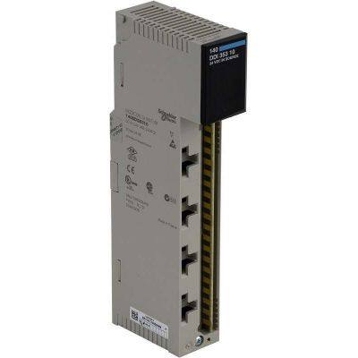
The SCHNEIDER 140DDI35310 is a high-performance industrial-grade digital input module, and a core I/O component of the Modicon M340 series PLCs. As a signal acquisition unit in industrial control systems, this module is specifically designed to receive digital signals from industrial sites (such as on-off signals from sensors, limit switches, buttons, and other devices) and convert them into digital signals recognizable by PLCs, enabling real-time monitoring of the operating status of on-site equipment. It is widely used in industrial automation fields with strict requirements for signal acquisition reliability and anti-interference performance, including automobile manufacturing, food and beverage processing, chemical and pharmaceutical production, water treatment, and metallurgical smelting.


Adopting a modular design and an industrial-grade enhanced circuit architecture, the product features high channel density, fast input response speed, strong anti-interference capability, and convenient installation and maintenance. As a standard compatible module for the M340 series PLCs, it can be seamlessly integrated into the system. When used with the Unity Pro programming software, it enables rapid configuration and debugging, providing a highly stable and cost-effective solution for the signal acquisition link of industrial control systems.


II. Technical Parameters


Parameter CategorySpecific SpecificationsDescription
Basic ConfigurationNumber of input channels: 32 independent channels; Channel grouping: 4 groups (8 channels per group); Input type: DC differential input; Compatible signals: Dry contact/wet contact signalsHigh channel density reduces rack space occupation; the grouping design facilitates fault troubleshooting and wiring management; compatible with different types of on-site signals
Input Electrical ParametersRated input voltage: DC 24V; Input voltage range: DC 18V-30V; Input current: Typical 3mA (at DC 24V); Turn-on threshold: ≤ DC 15V; Turn-off threshold: ≥ DC 5V


Wide voltage input adapts to power fluctuations in industrial sites; low input current reduces energy consumption; precise thresholds ensure the reliability of signal identification

Response Performance


Input response time: Configurable (0.1ms, 1ms, 10ms, 100ms); Default response time: 10ms; Synchronous acquisition: Supports synchronous acquisition of 8 channels within a group


Configurable response time adapts to different scenarios; fast response meets the needs of high-speed signal acquisition; synchronous acquisition ensures time consistency of signals in the same group

Anti-Interference & Isolation


Isolation method: Optical isolation between channel groups, and between groups and backplane bus; Isolation voltage: 2500V AC (rms) for 1 minute; Surge immunity: ±2kV (IEC 61000-4-5); ESD immunity: ±8kV (contact discharge), ±15kV (air discharge)


Multiple isolation designs suppress interference; strong surge and ESD immunity adapts to complex industrial electromagnetic environments, ensuring the accuracy of signal acquisition

Compatibility & Communication


Compatible PLCs: Modicon M340 series PLCs; Communication bus: M340 backplane bus; Data transmission rate: Max. 100Mbps for backplane bus; Programming software: Unity Pro V11 and above


Perfect compatibility with the M340 series; high-speed backplane bus ensures fast signal transmission; mainstream programming software lowers the development threshold

Environmental Parameters


Operating temperature: -25℃-70℃; Storage temperature: -40℃-85℃; Relative humidity: 5%-95% (no condensation); Protection class: IP20 (module itself); Vibration resistance: 10-500Hz, 2g (peak-to-peak)


Wide-temperature design adapts to high and low-temperature industrial scenarios; vibration resistance ensures the stability of cabinet installation; meets the operation requirements in harsh environments

Physical & Power Parameters


Dimensions: 100mm×140mm×210mm (L×W×H); Installation method: Slot installation in M340 series racks; Power supply method: Powered via backplane bus (DC 5V); Power consumption: ≤8W (full load); Weight: Approx. 300g


Standard rack installation simplifies system integration; backplane power supply reduces wiring; low-power design lowers system energy consumption

140DDI35310


III. Functional Features


  • High-Density Channels & Flexible Grouping: It integrates 32 digital input channels, adopting a grouping design of 4 groups (8 channels each). Each group of channels can be independently configured with response time, filtering parameters, and diagnostic functions, facilitating differentiated settings based on the type of on-site equipment. The high channel density design allows a single module to replace multiple low-channel modules, significantly reducing the occupation of M340 rack slots and lowering system hardware costs and cabinet space requirements. Channel wiring uses spring terminals or screw terminals (depending on the model), supporting quick wiring and disconnection to improve installation efficiency.

  • Configurable Response & Precise Acquisition: The input response time supports four configurable levels: 0.1ms, 1ms, 10ms, and 100ms. Users can flexibly adjust it via the Unity Pro software according to the signal type—selecting 0.1ms fast response for signals such as high-speed counting and fast limiting, and 10ms or 100ms response for signals such as ordinary buttons and status indicators to filter out interference. Each group of channels supports the synchronous acquisition function, ensuring that the acquisition time difference of 8 signals in the same group is ≤1μs, meeting the status monitoring needs of collaborative operations of multiple devices.

  • Multiple Isolation & Strong Anti-Interference: It adopts a dual optical isolation design of "between channel groups + between groups and backplane", with an isolation voltage of 2500V AC, effectively blocking the transmission of interference signals between different channel groups and between the module and the PLC host. The module is equipped with input filtering circuits and surge suppression circuits inside, which can resist ±2kV surge impacts and ±15kV ESD interference, complying with the IEC 61000-4 series EMC standards. It can still stably acquire signals in strong interference environments such as frequency converters and motors, avoiding false triggers or signal loss.

  • Comprehensive Diagnostics & Fault Early Warning: It has comprehensive diagnostic functions, which can real-time monitor the channel input status, power supply voltage, module communication status, and internal circuit faults. When a channel has an open circuit, short circuit, or overvoltage fault, the module uploads the fault information (including channel number and fault type) to the PLC host via the backplane bus, and lights up the fault indicator of the corresponding channel on the module panel. It supports channel disconnection diagnosis and power fault diagnosis, which can early warn potential faults and reduce downtime for maintenance.

  • Convenient Integration & Operation & Maintenance: As a standard module of the M340 series, it can be directly inserted into the I/O slot of the M340 rack, and automatically complete power supply and communication via the backplane bus without additional wiring or adapters. Through the Unity Pro software, full-process digital operations such as module parameter configuration, channel mapping, and diagnostic information viewing can be realized. It supports online modification of configurations such as response time and filtering parameters without power-off and restart. The module panel is equipped with channel status indicators (green on indicates signal on, red on indicates fault), allowing maintenance personnel to intuitively troubleshoot problems.

  • Wide-Temperature Resistance & High Reliability: It uses industrial-grade components and an enhanced PCB layout, with an operating temperature range covering -25℃-70℃, adapting to various environments such as cold workshops in northern regions, high-temperature workshops in southern regions, and outdoor control cabinets. The module has overvoltage and overcurrent protection functions. When the input voltage exceeds 30V DC, it automatically cuts off the input of the channel to avoid damage to internal circuits. The Mean Time Between Failures (MTBF) is ≥200,000 hours, meeting the requirements of long-cycle continuous operation in industrial applications.


IV. Working Principle


The core working principle of the SCHNEIDER 140DDI35310 digital input module is to convert on-site digital signals into digital signals processable by PLCs through the process of "signal acquisition → filtering and shaping → isolation and conversion → data transmission", as detailed below:
  1. Signal Input & Preprocessing Stage: On-site industrial digital signals (such as sensor on-off signals and button signals) are connected to the 32 input channels of the module through terminals. Depending on the signal type, either dry contact (requiring an external DC 24V power supply) or wet contact (with an internal detection power supply provided by the module) can be selected. The input signals first pass through an RC filtering circuit to filter out high-frequency interference and spike pulses in the signals, avoiding misidentification caused by interference signals. At the same time, the overvoltage protection circuit monitors the input voltage. When the voltage exceeds 30V DC, current-limiting protection is triggered to prevent module damage.

  2. Signal Shaping & Threshold Judgment Stage: The filtered signals enter the signal shaping circuit, which converts irregular input signals into standard square wave signals. Subsequently, the signals enter a voltage comparator and are compared with the preset turn-on threshold (≤15V DC) and turn-off threshold (≥5V DC): when the input voltage is ≤15V DC, it is judged as the "on" state (corresponding to the digital signal "1"); when the input voltage is ≥5V DC, it is judged as the "off" state (corresponding to the digital signal "0"); signals within the threshold range maintain the previous state to avoid frequent state switching caused by signal fluctuations.

  3. Isolation & Conversion & Synchronous Acquisition Stage: The digital signals after threshold judgment enter the optical isolation circuit, and electrical isolation between the input signals and the module's internal circuits is achieved through an optocoupler to block the transmission of interference signals. Each of the 4 groups of channels has an independent isolation circuit to ensure no crosstalk between signals of different groups. For groups with the synchronous acquisition function enabled, the internal clock synchronization circuit of the module controls the simultaneous isolation and conversion of 8 signals in the group, ensuring acquisition time consistency with a time difference ≤1μs. The converted digital signals are transmitted to the module's microprocessor.

  4. Data Processing & Diagnostics Stage: After receiving the digital signals from each channel, the microprocessor performs delay processing according to the configured response time parameters. For example, if the response time is set to 10ms, the microprocessor judges the signal state detected continuously for 10ms, and only the continuously stable state is recognized as a valid signal to further filter out interference. At the same time, the microprocessor executes diagnostic programs in real time to monitor the input current of each channel, the state of the isolation circuit, and the communication state of the backplane bus. If a channel short circuit (excessive current), open circuit (zero current), or communication interruption is detected, a fault code is generated immediately.

  5. Data Transmission & Status Feedback Stage: The microprocessor transmits valid signal data and fault diagnostic information to the PLC host via the M340 backplane bus. The host stores the signal data in the input image area for the logical operation of the user program. Meanwhile, the status indicators on the module panel feed back the working status of each channel in real time: a green indicator on means the channel signal is "1" (on), a green indicator off means the signal is "0" (off), and a red indicator on means there is a fault in the channel. Fault information can also be uploaded to the upper monitoring system via the PLC host to realize remote fault early warning and troubleshooting.


V. Common Faults & Solutions


Fault PhenomenonPossible CausesSolutions
No communication after module insertion, PLC fails to recognize the module1. The module is not fully inserted into the rack slot, resulting in poor backplane contact; 2. Fault of the rack backplane bus; 3. Fault of the module power supply circuit; 4. Incompatibility between the module and PLC firmware versions
  1. Power off and reinsert the module to ensure the module latch is fully locked; check if the slot contacts are oxidized and clean them with alcohol; 2. Insert the module into another normal rack slot for testing; if it works normally, repair the original rack backplane; 3. Measure the DC 5V power supply voltage of the backplane bus to confirm normal power supply, and contact after-sales service to inspect the module power supply circuit; 4. Upgrade the PLC firmware to the latest version supported by Unity Pro to ensure compatibility


No response from a channel signal, indicator not on1. Fault of on-site equipment or disconnection of signal cables; 2. Incorrect channel wiring (reversed positive and negative poles); 3. Input voltage of the channel exceeds the range; 4. Fault of the internal circuit of the channel
  1. Detect the output signal of on-site equipment (such as sensors) and replace the faulty equipment; use a multimeter to measure the continuity of the signal cable and replace the disconnected cable; 2. Check the positive and negative wiring of the channel against the wiring diagram and correct the wiring error; 3. Measure the input voltage to ensure it is within the range of 18-30V DC and adjust the on-site power supply; 4. Connect the signal of this channel to another normal channel; if it works normally, contact after-sales service to repair the faulty channel of the module


Frequent false triggering of channel signals, indicator flashing1. Severe electromagnetic interference on-site; 2. Too short channel response time setting; 3. Input signal voltage is close to the threshold (5-15V DC); 4. Unreasonable configuration of filtering parameters
  1. Replace the signal cable with a shielded twisted pair, and ground the shield at one end (ground resistance ≤4Ω); add a signal isolator; 2. Adjust the channel response time from 0.1ms/1ms to 10ms/100ms via the Unity Pro software; 3. Adjust the on-site power supply to ensure the input voltage is ≥18V (when on) or ≤5V (when off); 4. Optimize the channel filtering parameters and increase the filtering time constant


Fault of an entire group of channels, fault indicator on1. Incorrect wiring or disconnection of the common terminal of the group; 2. Fault of the isolation circuit between groups; 3. Fault of the internal power supply of the module (powering this group); 4. Fault of the common power supply of on-site equipment
  1. Check the wiring of the common terminal of the group, re-tighten or replace the disconnected wire; 2. Contact after-sales service to inspect the inter-group isolation circuit of the module and replace the module if necessary; 3. Measure the group power supply voltage inside the module, and repair after confirming the power supply fault; 4. Check the common DC 24V power supply of on-site equipment and replace the faulty power module


Module suddenly goes offline during operation, communication interrupted1. Loose contact between the module and the rack (caused by vibration); 2. Excessive voltage fluctuation of the backplane bus; 3. Strong electromagnetic impact on the industrial site (such as lightning strike); 4. Fault of the module microprocessor
  1. Power off and re-fix the module; check if the rack latches are damaged and replace the damaged latches; 2. Measure the DC 5V voltage of the backplane bus to ensure the fluctuation is ≤±0.5V and add a power filter; 3. Check if the module has been subjected to lightning strike or strong impact and replace the damaged module; 4. Restart the PLC and the module; if it still goes offline, contact after-sales service to inspect the microprocessor


Channel indicator is on but the PLC has no corresponding signal1. Incorrect mapping between module channels and PLC input image area; 2. Too long response time setting, signal not updated; 3. Data loss in communication between the module and PLC; 4. Error in PLC program logic1. Check the channel mapping configuration via the Unity Pro software and correct the mapping address; 2. Shorten the channel response time or observe the signal update after the response time expires; 3. Check the backplane bus connection, clean the contacts, and reduce communication interference; 4. Debug the PLC program and check if the input image area reading logic is correct
Product Tags: 140DDI35310

Send Inquiry to This Supplier

Message
0/5000
Want the best price? Post an RFQ now!
1Yr
Business Type
Trading Company
Year Established
2014
Factory Size
1,000-3,000 square meters
Product Certifications
SA8000