Material
Other, Global universal model
Condition
Other, Global universal model
Task
Other, Global universal model
Mathematical Model
Other, Global universal model
Signal
Other, Global universal model
Customized
Non-Customized
Structure
Other, Global universal model
Operating Temperature
-25℃-70℃
Relative Humidity
5%-95% (non-condensing)
Dimensions
100mm×140mm×210mm
I. Overview
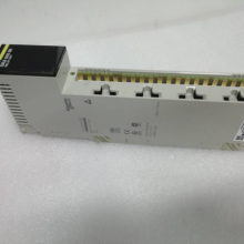
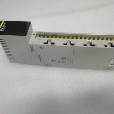
Schneider 140DRA84000 is a high-precision analog input module, a core I/O component of the Modicon Quantum series control system, specifically designed for accurate acquisition of continuous process parameters in industrial scenarios. Serving as a key signal hub between the control system and on-site analog sensing devices (such as pressure transmitters, temperature sensors, level transmitters, flow sensors, etc.), this module efficiently converts continuous analog signals (current or voltage) output by on-site sensors into digital signals recognizable by the control system. It provides stable and reliable data support for closed-loop regulation, status monitoring, and safety interlocking in industrial processes.
It is widely used in industrial automation fields with strict requirements for analog acquisition accuracy and stability, including petrochemicals, chemical pharmaceuticals, power energy, metallurgical smelting, food processing, and precision manufacturing. The product adopts a modular reinforced design and an industrial-grade circuit architecture, featuring core advantages such as independent multi-channel configuration, high-precision analog-to-digital (AD) conversion, multiple isolation protections, full-dimensional diagnosis, and convenient integration. As a standard-compatible module for the Modicon Quantum series, it can be seamlessly integrated into the system rack. When used with Concept or EcoStruxure Control Expert programming software, it enables rapid parameter configuration and fault localization, offering a cost-effective solution for analog signal acquisition in complex industrial environments.
II. Technical Parameters

III. Functional Features
Independent Single-Channel Configuration and Wide Scenario Adaptability: The 8 channels support independent configuration of input type (current/voltage) and signal range per channel. For example, channels 1-4 can be configured for 4-20mA DC to acquire pressure and level signals, while channels 5-8 can be set to 0-10V DC for temperature and flow signal acquisition. This eliminates the need to replace modules to meet the acquisition requirements of multiple sensor types. The current input impedance is ≤100Ω, compatible with transmitters for long-distance transmission (minimal impact from wire resistance); the voltage input impedance is ≥100kΩ, preventing attenuation of signals from high-impedance sensors. Independent zero-point and full-scale calibration for each channel allows precision fine-tuning for different sensors, improving the accuracy of acquired data.
High-Precision AD Conversion and High-Speed Sampling: Equipped with a 16-bit high-precision AD conversion chip and enhanced signal conditioning circuits, the sampling accuracy reaches ±0.05% FS (at room temperature) and maintains ±0.1% FS even within the 0℃-60℃ wide temperature range, meeting the needs of precision process control scenarios (e.g., pressure acquisition for chemical reactors). The module has a built-in low-temperature-drift reference voltage source (temperature drift ≤50ppm/℃), ensuring stable acquired data with no significant drift when the ambient temperature changes. The single-channel sampling rate is 100Hz, and the full-channel parallel sampling rate is 500Hz, enabling rapid capture of changes in dynamic process parameters (e.g., pipeline pressure fluctuations, reaction temperature rise curves). This provides real-time data support for the control system and avoids control delays.
Multiple Safety Protections and High Reliability: Each channel integrates a four-fold safety protection mechanism. In case of overcurrent, the built-in current-limiting resistor restricts the input current to within 30mA, preventing damage to the AD conversion chip due to sensor short circuits or overloads. The input terminal uses a combination of varistors and clamping diodes to limit overvoltage to within ±36V, protecting the input circuit. Polarity protection is supported—even if the sensor’s positive and negative wires are reversed, the module will not be damaged, reducing the risk of wiring errors. Continuous short-circuit protection ensures the module remains undamaged during line short circuits and automatically resumes normal acquisition after the fault is eliminated. The module uses industrial-grade high-stability components, with a Mean Time Between Failures (MTBF) of ≥250,000 hours, ensuring long-term stable operation.
Group Isolation and Enhanced Anti-Interference: The 8 channels are divided into 2 independent isolation groups (4 channels per group). 2500V AC optoelectronic isolation is used between groups, and capacitive isolation is applied between channels and the backplane bus. This completely blocks interference transmission between different sensor circuits, making it particularly suitable for complex scenarios with mixed access to multiple sensor types (e.g., simultaneous acquisition of pressure, temperature, and flow signals). The module integrates EMC-enhanced circuits, including surge suppression diodes, electromagnetic shielding layers, RC filter circuits, and signal isolation amplifiers. Compliant with the EN 61326-2-3 EMC standard, it can resist ±2kV surge impacts and high-frequency electromagnetic interference. Even in high-interference environments such as metallurgy and chemical industries, it can acquire stable analog signals without fluctuations or distortion.
Full-Dimensional Diagnosis and Intelligent Early Warning: It features a three-tier diagnostic system (channel-level, isolation group-level, and system-level) and enables multiple fault diagnoses through high-precision current sampling and voltage detection: input current exceeding 30mA is judged as overcurrent; current close to 0 with normal sensor power supply is identified as sensor disconnection; input voltage exceeding ±36V is classified as overvoltage; and failed AD conversion data verification is deemed a conversion fault. When a fault occurs, detailed information (including channel number and fault type) is immediately uploaded to the PLC host via the backplane bus to trigger an audible and visual alarm. The LED indicator of the corresponding channel flashes red, allowing operation and maintenance personnel to quickly locate the fault point without using professional instruments. It also supports real-time feedback of acquired data, sending the digital data after AD conversion back to the control system to achieve closed-loop verification of "signal acquisition - data feedback".
Convenient Installation and Operation & Maintenance Optimization: It adopts Modicon Quantum standard rack slot installation. After the module is inserted into the rack, it is automatically locked by a mechanical buckle, and the backplane bus completes power supply, communication, and address assignment automatically—no additional wiring is required, improving installation efficiency by over 40% compared to traditional modules. Two terminal types are optional: spring-type and screw crimp. Spring-type terminals are suitable for 0.5mm²-2.5mm² wires, offering fast wiring and vibration resistance; screw crimp terminals are compatible with 0.75mm²-4mm² wires, ensuring secure and reliable wiring. Each channel is equipped with an independent LED indicator: green on indicates normal acquisition, and red flashing indicates a fault. Operation and maintenance personnel can visually judge the channel’s operating status without professional instruments.
Seamless System Integration and Flexible Debugging: As a standard module of the Modicon Quantum series, it achieves mechanical, electrical, and software seamless compatibility with Quantum PLC hosts, allowing direct integration into existing control systems without additional adaptation devices. When used with Concept or EcoStruxure Control Expert programming software, it provides a graphical configuration interface, supporting rapid configuration of parameters such as input type, signal range, sampling rate, calibration parameters, and fault thresholds. It also supports online calibration, enabling precision calibration without removing the module. The software has a built-in sensor database, supporting quick adaptation to sensors of common brands and simplifying the debugging process.
IV. Working Principle
The core working principle of the Schneider 140DRA84000 analog input module is to achieve accurate acquisition of on-site continuous process parameters by the PLC system through a closed-loop process of "signal access - preprocessing - AD conversion - data transmission - fault diagnosis", as detailed below:
Signal Access and Preprocessing: Analog signals (current or voltage) output by on-site sensors (e.g., pressure transmitters, temperature sensors) are connected to the corresponding channels via terminals. The signals first enter the input protection circuit: varistors clamp voltage during overvoltage, current-limiting resistors restrict current during overcurrent, and polarity protection diodes block reverse current in case of reverse connection—all to protect subsequent circuits. The protected signals then enter the signal conditioning circuit: instrumentation amplifiers amplify weak signals (e.g., 4-20mA small current signals), and RC filter circuits remove high-frequency noise and spike pulses to ensure signal purity. Meanwhile, according to the input type configured for the channel, current or voltage signals are uniformly conditioned into standard voltage signals (e.g., 0-5V) recognizable by the AD conversion chip.
AD Conversion and Data Processing: The conditioned standard voltage signals are transmitted to the 16-bit AD conversion chip, which converts the analog signals into corresponding digital signals (e.g., converting 4-20mA current signals into digital values ranging from 0 to 65535). The converted digital signals are transmitted to the module’s microprocessor after isolation by the optoelectronic isolation unit, preventing interference from sensor circuits from spreading to the core circuits. The microprocessor performs scaling conversion on the digital signals: based on the channel’s preset signal range (e.g., 4-20mA corresponding to 0-10MPa pressure), it converts the digital values into actual physical quantity values. Simultaneously, linearity correction and temperature compensation are performed to eliminate system errors and the impact of temperature drift, improving data accuracy.
Data Transmission and Status Feedback: The processed physical quantity data is transmitted to the PLC host via the Modicon Quantum backplane bus for use by control programs or data storage. At the same time, the microprocessor backs up the original AD conversion data and the processed physical quantity data, which serve as the basis for fault diagnosis. The module feeds back its operating status to the host in real time via the bus, including the acquisition status of each channel, isolation group status, and power status. The host can monitor the module’s operation in real time through programming software. If communication anomalies occur during data transmission, the microprocessor immediately generates communication fault information and uploads it to the host to trigger an alarm.
Isolation and Interference Suppression: Optoelectronic isolation is used between the signal conditioning circuits of each group of channels and the microprocessor, ensuring that interference from sensor circuits does not spread to the module’s core control circuits. Capacitive isolation between channels and the backplane bus further blocks interference interaction between the bus side and the input side. The core circuits of the module are wrapped in an electromagnetic shielding layer to resist external electromagnetic radiation interference. Signal isolation amplifiers isolate the conditioned signals from the core circuits, ensuring accurate sampling data. Multiple isolation and interference suppression measures ensure the module operates stably in complex electromagnetic environments, with acquired data unaffected by interference.
Fault Diagnosis and Early Warning: The microprocessor executes the fault diagnosis program in real time, continuously monitoring parameters such as input current, voltage signals, AD conversion data, and module power supply voltage of each channel. When faults such as overcurrent, overvoltage, short circuit, sensor disconnection, or AD conversion failure are detected, the microprocessor immediately generates a fault code, marks the faulty channel and fault type, and uploads the fault information to the PLC host via the backplane bus. The host triggers an audible and visual alarm or safety interlocking action according to preset logic. At the same time, the microprocessor controls the LED indicator of the corresponding channel to switch to red flashing, reminding operation and maintenance personnel to handle the fault promptly. After the fault is eliminated, the module automatically resumes normal acquisition.
V. Common Faults and Solutions