Home > Electrical & Electronics > Electrical Control System > SCHNEIDER 140DDO88500 DC Discrete Output Module

SCHNEIDER 140DDO88500 DC Discrete Output Module

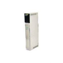
SCHNEIDER 140DDO88500 DC Discrete Output Module photo-1
Negotiable MOQ: 1 Piece (Price negotiable depending on order volume and customization)
Key Specifications
Get Latest Price
Material:
Other, Global universal model
Condition:
Other, Global universal model
Task:
Other, Global universal model
Payment & Shipping
Payment Methods:
Port of Shipment:
guizhou
Delivery Detail:
Delivery time depends on order quantity.
Material Other, Global universal model
Condition Other, Global universal model
Task Other, Global universal model
Mathematical Model Other, Global universal model
Signal Other, Global universal model
Customized Non-Customized
Structure Other, Global universal model
Operating Temperature -25℃-70℃
Relative Humidity 5%-95% (non-condensing)
Dimensions 100mm×140mm×210mm

I. Overview


Schneider 140DDO88500 is a digital output module specifically designed for the precise control and safe operation of medium and high-power discrete actuators in industrial scenarios. Serving as a key control hub between the control system and on-site digital execution equipment (such as AC contactors, high-power solenoid valves, motor starters, and alarm lights), this module can efficiently convert digital commands from the control system into high-voltage signals that drive actuators. It also integrates multiple safety protections and full-dimensional fault diagnosis functions, providing stable and reliable control support for sequence control of industrial processes, equipment start-stop, and safety interlocking.


It is widely used in industrial automation fields with strict requirements for the reliability and stability of digital output control, including petrochemicals, power generation, metallurgical rolling, automobile manufacturing, heavy machinery, and municipal engineering. The product adopts a modular reinforced design and an industrial-grade circuit architecture, featuring wide load adaptation, multiple isolation protections, convenient integration, and long service life. As a standard compatible module for the Modicon Quantum series, it can be seamlessly integrated into the system rack. When used with Concept or EcoStruxure Control Expert programming software, it enables rapid parameter configuration and fault localization, offering a cost-effective solution for medium and high-power load control in complex industrial environments.


II. Technical Parameters


Parameter CategorySpecific SpecificationsDescription
Channel ConfigurationNumber of channels: 8 independent digital outputs; Output type: Relay output (Single-Pole Single-Throw Normally Open, SPST-NO); Wiring method: Spring-type or screw crimp terminals (optional), independent contact terminals for each channel; Isolation method: Optoelectronic isolation between channels, capacitive isolation between channels and backplane bus, isolation voltage of 2500V AC (rms)SPST-NO contacts are suitable for conventional control circuits; the independent isolation design effectively blocks interference between channels; optional wiring methods meet different construction requirements.
Load Driving Parameters


Rated load voltage: AC 250V / DC 30V; Rated load current: 8A (continuous per channel), 16A (short-term per channel, ≤0.5s); Contact life: ≥1 million times (resistive load), ≥100,000 times (inductive load); Output response time: ≤15ms (from command issuance to contact action); Minimum switching current: 10mA (DC 5V)


High-current driving capability is suitable for medium and high-power loads; short-term peak current meets the needs of impact loads such as motor starting; long-life design reduces maintenance costs.

Safety Protection Parameters


Overcurrent protection: Built-in resettable overcurrent protector (9A±1A) for each channel; Overvoltage protection: Metal Oxide Varistor (MOV) connected in parallel between contacts; Surge suppression: Compliant with IEC 61000-4-5 standard, ±2kV (line to ground); Short-circuit protection: No damage for 30s continuous short circuit, automatic recovery after fault elimination


Multiple protection mechanisms prevent module damage caused by load faults; resettable protectors eliminate the need for frequent replacement; MOV effectively absorbs switching surges.

Isolation and Anti-Interference


Isolation voltage: 2500V AC (rms) between channels and between channels and backplane, for 1 minute; Electromagnetic interference resistance: Compliant with EN 61326-2-3 standard; ESD protection: ±15kV (air discharge), ±8kV (contact discharge); Radiated interference: Compliant with CISPR 22 Class A standard


High-strength isolation and EMC protection design is suitable for industrial environments with strong interference such as metallurgy and chemical industry, ensuring stable and error-free action of output signals.

Compatibility and Programming


Compatible systems: Schneider Modicon Quantum series PLC; Programming software: Concept V2.6 and above, EcoStruxure Control Expert V15 and above; Diagnostic functions: Channel-level overcurrent, short circuit, contact fault diagnosis, module power fault alarm; Status indication: LED indicator for each channel (green on = contact closed, off = open, red flashing = fault)


Seamless compatibility with Quantum systems; supported by mainstream programming software; comprehensive diagnostic functions improve operation and maintenance efficiency; LED indicators facilitate on-site observation.

Environmental and Physical Parameters


Operating temperature: 0℃-60℃; Storage temperature: -40℃-85℃; Relative humidity: 5%-95% (no condensation); Protection class: IP20 (module itself); Installation method: Modicon Quantum standard rack slot installation; Power consumption: ≤18W (full load); Weight: Approximately 650g


Wide-temperature design is suitable for conventional industrial environments; standard rack installation simplifies integration; reasonable power consumption controls system energy consumption.

140CPS12400


III. Functional Features


  • Strong Load Driving and Flexible Adaptation: Adopts an 8-channel independent Single-Pole Single-Throw Normally Open (SPST-NO) relay output design. Each channel has a continuous load current of 8A and a short-term peak current of 16A, which can directly drive medium and high-power executive equipment such as AC contactors and high-power solenoid valves without additional intermediate relays, simplifying the control circuit structure. It supports AC 250V and DC 30V wide-voltage loads, is compatible with actuators of both AC and DC power supply types, and adapts to diverse industrial control scenarios. The minimum switching current is as low as 10mA (DC 5V), which can stably drive micro-current loads such as small indicator lights, realizing mixed control of loads with different power levels by the same module.

  • Multiple Safety Protections and High Reliability: Each channel integrates a triple safety protection mechanism, with a built-in 9A resettable overcurrent protector. When the load current exceeds the rated value, it acts quickly to cut off the circuit, and can be restored to use by manual reset after the fault is eliminated, without replacing fuses. A Metal Oxide Varistor (MOV) is connected in parallel between the contacts to effectively absorb the surge voltage generated during load switching and avoid arc erosion of the contacts. For short-circuit faults, the module has a 30s continuous short-circuit withstand capability to prevent module burnout caused by instantaneous short circuits. The relay contacts are made of silver-tin alloy material, with a service life of more than 1 million times for resistive loads and 100,000 times for inductive loads, greatly reducing the frequency of maintenance and replacement and improving system operation stability.

  • Full Isolation Design and Enhanced Anti-Interference: Adopts a dual isolation design between channels and between channels and the backplane bus, with an isolation voltage of 2500V AC, which completely blocks the interference transmission between different load circuits, especially suitable for complex scenarios where multiple types of loads are mixed and connected. The module integrates an EMC-enhanced circuit, including surge suppression diodes, electromagnetic shielding layers, and RC filter networks. It has passed the EN 61326-2-3 electromagnetic compatibility certification, and can resist ±2kV surge impacts and high-frequency electromagnetic interference. It can still stably output control signals in strong interference environments with concentrated frequency converters and high-power motors, without contact misoperation or signal loss. The ESD protection level reaches ±15kV (air discharge), effectively dealing with electrostatic interference in industrial sites.

  • Full-Dimensional Diagnosis and Intelligent Early Warning: Equipped with dual diagnostic functions at the channel level and system level, realizing multiple fault diagnoses through high-precision current sampling and contact status monitoring. When the load current exceeds 9A, it is determined as an overcurrent fault; when the current abnormally increases to the short-circuit threshold, a short-circuit alarm is triggered; the contact feedback circuit is used to detect faults such as relay contact adhesion and welding; at the same time, the module power supply voltage status is monitored. When a fault occurs, detailed information including the channel number and fault type is immediately uploaded to the PLC host through the backplane bus to trigger a system alarm; the LED indicator of the corresponding channel on the module panel flashes red to visually indicate the fault location, allowing operation and maintenance personnel to quickly locate the fault point and shorten the troubleshooting time.

  • Convenient Installation and Operation & Maintenance Optimization: Adopts Modicon Quantum standard rack slot installation. After the module is inserted into the rack, it is automatically locked by a mechanical buckle, and the backplane bus automatically completes power supply, communication, and address assignment without additional wiring, improving installation efficiency by more than 40% compared with traditional modules. It supports two optional terminal types: spring-type and screw crimp. Spring-type terminals are suitable for 0.5mm²-2.5mm² wires, with fast wiring speed and vibration resistance; screw crimp terminals are suitable for 0.75mm²-4mm² wires, with firm and reliable wiring. Each channel is equipped with an independent two-color LED indicator: green on indicates the contact is closed (actuator action), off indicates open (actuator stop), and red flashing indicates a fault. Operation and maintenance personnel can visually judge the channel operation status without professional instruments.

  • Seamless System Integration and Stable Operation: As a standard module of the Modicon Quantum series, it achieves mechanical, electrical, and software triple seamless compatibility with the Quantum PLC host, and can be directly integrated into the existing control system without additional adaptation devices. When used with Concept or EcoStruxure Control Expert programming software, it provides a graphical configuration interface, supporting custom configuration of parameters such as output delay, fault reset method, and contact action logic. Users can quickly complete module debugging according to on-site control requirements. The module adopts industrial-grade high-stability components and an enhanced PCB layout, with a Mean Time Between Failures (MTBF) of ≥250,000 hours. It can operate stably for a long period in a wide temperature environment of 0℃-60℃, adapting to complex working conditions in industrial sites.


IV. Working Principle


The core working principle of the Schneider 140DDO88500 digital output module is to realize the precise control of on-site medium and high-power actuators by the PLC system through a closed-loop process of "command reception - drive control - contact action - status feedback - fault diagnosis", as follows:
  1. Command Reception and Preprocessing: The module receives digital output commands ("1" for close command, "0" for open command) sent by the PLC host through the Modicon Quantum backplane bus. The commands are transmitted to the module microprocessor through a differential communication interface. The microprocessor performs CRC verification on the commands to confirm the integrity of the commands and the matching of channel addresses, and then triggers the relay drive program of the corresponding channel according to the preset output delay parameters (configurable through software). If the command is invalid or the address does not match, communication fault information is immediately generated and uploaded to the host.

  2. Relay Driving and Contact Action: According to the command, the drive program controls the relay drive circuit of the corresponding channel. When receiving a "close" command, the drive circuit outputs a constant current to the relay coil. The coil is energized to generate an electromagnetic field, which attracts the armature to drive the contact action. The Single-Pole Single-Throw Normally Open (SPST-NO) contact closes, providing working power for the load and driving the actuator (such as a contactor or solenoid valve) to act. When receiving an "open" command, the drive circuit cuts off the power supply to the coil. The armature resets under the action of the return spring, the contact returns to the normally open state, the load circuit is disconnected, and the actuator stops working. The drive circuit adopts a constant current drive design to ensure the stability of the relay coil current and avoid unreliable contact action caused by voltage fluctuations.

  3. Status Feedback and Signal Isolation: After the relay contact acts, the contact status feedback circuit inside the module collects the actual on-off status of the contact in real time. The feedback signal is transmitted to the microprocessor after being isolated by the optoelectronic isolation unit, preventing the high-voltage interference of the load circuit from being transmitted to the core control circuit of the module. The microprocessor compares the feedback status with the issued command. If they are consistent, the action is determined to be normal, and the status information is transmitted back to the PLC host through the backplane bus to complete the closed-loop control of "command - action - feedback". If they are inconsistent (e.g., the command is close but the feedback is open), it is determined to be a contact fault, and the fault diagnosis program is triggered immediately.

  4. Load Protection and Interference Suppression: During the operation of the load, the module monitors the load current of each channel in real time. After the current signal is converted into a voltage signal by the sampling resistor, it is transmitted to the overcurrent detection circuit and the short-circuit detection circuit. When the load current exceeds 9A, the overcurrent detection circuit triggers the resettable protector to act and cut off the load circuit. When a short-circuit fault occurs, the short-circuit detection circuit immediately sends a signal to the microprocessor. The microprocessor controls the drive circuit to cut off the power supply to the relay coil and triggers a short-circuit alarm at the same time. For the surge voltage generated during the switching of inductive loads, the MOV varistor connected in parallel between the contacts is quickly turned on to absorb the surge energy and protect the relay contacts from arc erosion. The EMC filter circuit inside the module filters out high-frequency interference signals to ensure stable output signals.

  5. Fault Diagnosis and Information Upload: The microprocessor executes the fault diagnosis program in real time and continuously monitors parameters such as the current data of each channel, contact feedback signals, and module power supply voltage. When faults such as overcurrent, short circuit, contact adhesion, and power supply abnormality are detected, the microprocessor immediately generates a fault code, marks the fault channel and fault type, and uploads the fault information to the PLC host through the backplane bus. The host triggers an audible and visual alarm or safety interlocking action according to the preset logic. At the same time, the microprocessor controls the LED indicator of the corresponding channel to switch to a red flashing state, reminding operation and maintenance personnel to handle the fault in time. After the fault is eliminated, the module can be restored to normal operation through software or manual reset.


V. Common Faults and Solutions


Fault PhenomenonPossible CausesSolutions
PLC cannot recognize the module after it is inserted into the rack1. The module is not fully inserted into the rack, resulting in poor contact of backplane contacts; 2. Fault of the rack backplane bus or abnormal power supply voltage; 3. Incorrect module address DIP switch setting, causing address conflict with other modules in the system; 4. Incompatibility between the module and PLC firmware versions; 5. Fault of the internal communication circuit of the module
  1. Power off, reinsert the module to ensure the buckle is fully locked, and clean the oxide layer on the backplane contacts with anhydrous alcohol; 2. Measure the backplane power supply voltage (normal 24V±10%), replace the faulty power module, and insert the module into another slot to test the bus status; 3. Reset the address DIP switch according to the system configuration table to ensure a unique address; 4. Upgrade the PLC or module firmware to a compatible version; 5. Test with a spare module, and contact Schneider after-sales service for repair if the fault is confirmed


No output from a single channel, actuator does not act1. The resettable overcurrent protector of the corresponding channel trips; 2. Relay coil damage or contact adhesion/welding; 3. Load line disconnection or poor terminal contact; 4. Load short circuit causing module protection; 5. Fault of the module drive circuit
  1. Find the protector of the corresponding channel, press the reset button to reset, and check the cause of load overcurrent before resetting; 2. Measure the relay coil resistance with a multimeter (normally tens to hundreds of ohms), measure the contact on-off status, and repair or replace the module if damaged; 3. Check the load wiring, re-tighten the terminals, and replace the disconnected wire; 4. Power off, measure the load resistance, check and repair the short-circuit point, and retry after resetting the protector; 5. Switch the signal to a normal channel for testing, and send for repair if the drive circuit fault is confirmed


Channel LED flashes red, indicating overcurrent fault1. Excessive load power, exceeding the rated current of the channel (8A); 2. Load jamming causing current increase (e.g., motor stalling, solenoid valve jamming); 3. Parameter drift of the resettable protector; 4. False alarm caused by fault of the current sampling circuit
  1. Verify the rated current of the load; if it exceeds 8A, add an intermediate relay or replace with a module of larger capacity; 2. Check the load mechanical structure, eliminate jamming faults, and reset the protector after repair; 3. Replace the resettable protector of the same specification and retest; 4. Replace the module to a normal slot; if the false alarm still occurs, contact after-sales service to repair the sampling circuit


Frequent relay contact damage, short service life1. No external surge suppression device for inductive loads; 2. Frequent start-stop of the load leading to increased contact wear; 3. Load voltage exceeding the module rated value; 4. Mismatch between relay contact selection and load type
  1. Install an external RC absorption circuit or surge suppressor for inductive loads (e.g., motors, solenoid valves); 2. Optimize the control logic to reduce unnecessary frequent start-stop and extend the contact service life; 3. Verify the load voltage to ensure it does not exceed the rated value of AC 250V/DC 30V; 4. Replace with a relay module suitable for inductive loads or add an intermediate relay for isolation


Unstable output signals of multiple channels, frequent start-stop of actuators1. Severe on-site electromagnetic interference (e.g., close to frequency converters, high-power motors); 2. Poor module grounding; 3. Excessive fluctuation of power supply voltage; 4. Too small output delay parameter setting1. Replace with twisted-pair shielded wires, ground the shield layer at one end, keep the module away from interference sources, and add a signal isolator if necessary; 2. Check the module grounding circuit to ensure the grounding resistance is ≤4Ω, and adopt an independent grounding method; 3. Install a voltage stabilizer or filter for the module power supply to stabilize the power supply voltage; 4. Increase the output delay parameter (e.g., from 10ms to 50ms) through programming software to suppress signal fluctuation
Product Tags: 140DDO88500

Send Inquiry to This Supplier

Message
0/5000
Want the best price? Post an RFQ now!
1Yr
Business Type
Trading Company
Year Established
2014
Factory Size
1,000-3,000 square meters
Product Certifications
SA8000