

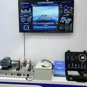
PT300SAT Balancing Alignment Simulator


Related Products
-
 PT200 Vibration Analysis Training System Gearbox Prognostics SimulatorUS$ 2980MOQ: 1 Combo
 -
SAT500 Shaft Alignment Trainer Portable Vibration SimulatorUS$ 2980MOQ: 1 Combo
-
PT100 Bearing Fault Simulator-alenian Machinery Fault SimulatorUS$ 2980MOQ: 1 Combo
-
PT300 Machinery Fault Simulator–LiteUS$ 3980MOQ: 1 Combo
-
PT300PRO Machine Vibration SimulatorUS$ 2980MOQ: 1 Combo
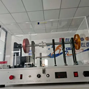
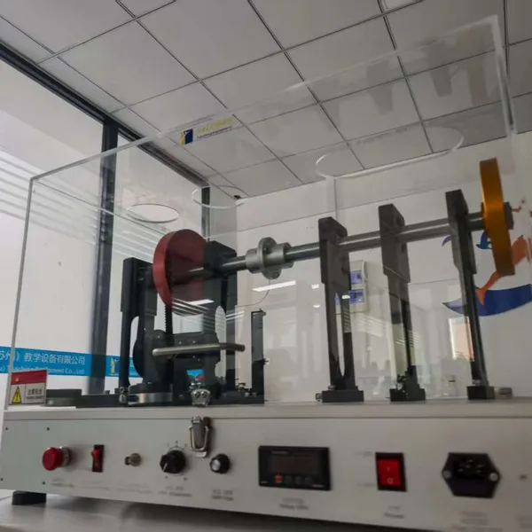
The PT300-SAT shaft alignment and dynamic balance simulation test bench is specifically designed for in-depth research on bearing faults, misalignment, and unbalance issues in mechanical faults, which account for over 90% of mechanical faults. During the initial design of the test bench, full consideration was given to minimizing additional changes in external conditions when replacing components. This allows for the acquisition of useful data under the same working conditions, ensuring the accuracy and consistency of analysis results.
Practice of vibration measurement and selection of vibration sensor positions;
Impact of rotor unbalance on vibration;
Impact of shaft misalignment on vibration;
Simulation of soft foot faults;
Simulation of belt faults;
Simulation of bearing faults (bearing inner ring fault, bearing outer ring fault, bearing cage fault, bearing rolling element fault, and comprehensive bearing fault);
Simulation of single-plane and double-plane dynamic balance.
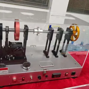
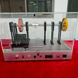
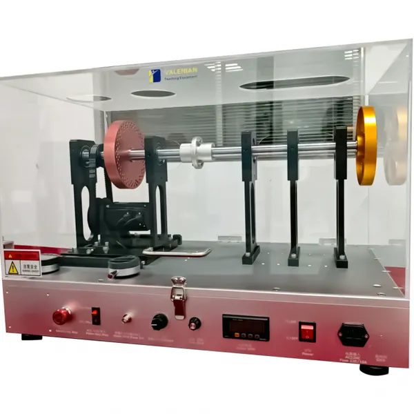
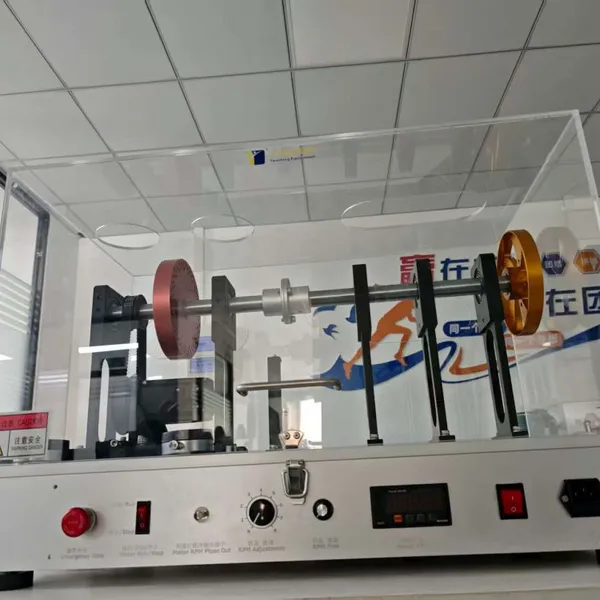
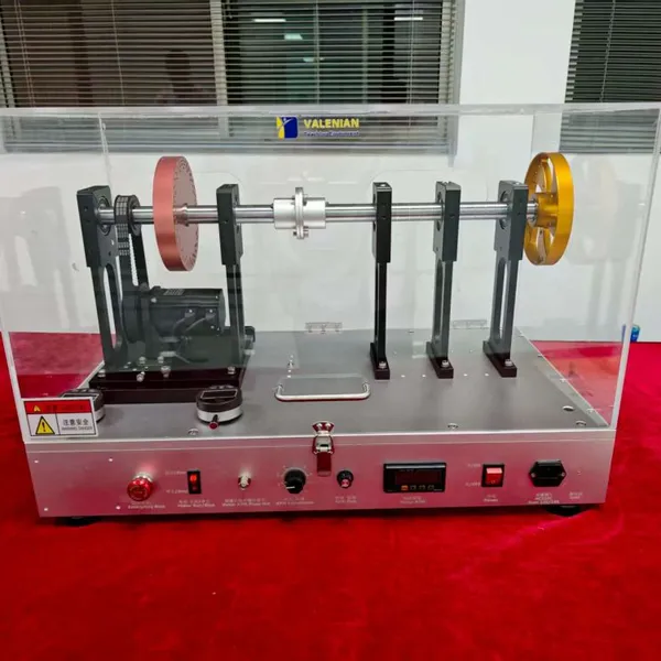
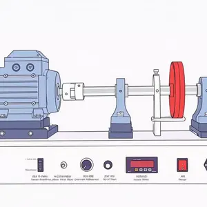
The test bench mainly consists of an aluminum platform base plate, a centering indicator dial gauge, a permanent magnet brushless motor, a drive governor, rolling bearings, a rotor system, a coupling, a pulley, a synchronous belt, a dynamic balance rotor disk, a rotor impeller, and an acrylic protective cover.
For the motor belt transmission system, when the motor is directly connected to the rotor, it is almost impossible to achieve perfect shaft alignment, so there will be a certain tolerable residual deviation. When the motor is connected to the rotor through a belt transmission, it is conducive to fine dynamic balance work because the misaligned components are completely eliminated, leaving only vibration components caused by unbalance. Therefore, in on-site dynamic balance work in industrial settings, most rotors are driven by belts.
To simulate double-plane balance experiments, the equipment is equipped with two rotor disks as standard at the center of the shaft. In addition, a third rotor disk is available as an optional accessory.
The rotor disk has 18 M5 screw holes on two different circumferential diameters:
Diameter d1 = 140 mm, with 36 M5 holes at 10° intervals;
Diameter d2 = 130 mm, with 36 M5 holes at 10° intervals;
Diameter d3 = 120 mm, with 18 M5 holes at 20° intervals.
The fan rotor is a disk with 5 blades, designed to resemble fan blades. Each blade is provided with 15 holes, which are not arranged in completely opposite positions, thus enabling the study of the additional effects of mass distribution.
Diameter d1 = 136 mm, with 15 M5 holes at 24° intervals;
Diameter d2 = 65 mm, with 5 M6 holes at 72° intervals.
The centering base mechanism is designed to allow the motor base to move in four directions when testing centering effects, thereby artificially creating misalignment. In addition, the equipment is equipped with a dial indicator for accurately positioning the base feet during position calibration. Users can set misalignment states through this mechanism and accurately restore them to the original centering state.
Adjustment knobs: for fine-tuning the centering state;
Dial indicator: for accurately measuring and indicating the amount of misalignment.
After slightly loosening the fixing bolts in the centered state, users can change the centering state through the adjustment knobs. This is because the base plate used to create misalignment is pressed tightly by strong springs during operation. Through the indicated value of the dial indicator, users can accurately achieve parallel misalignment or angular misalignment, and compare and analyze the changes in vibration signal patterns with misalignment states in real-time.
Four-way movement: The motor base can move in four directions to flexibly create misalignment;
Dial indicator indication: Accurately measures the amount of misalignment to ensure operational accuracy;
Real-time analysis: Observes changes in vibration signal patterns in real-time for easy comparison and analysis;
Centering restoration: Can be accurately restored to the original centering state after testing to ensure equipment stability.
The centering base is designed to simulate various misalignment conditions, including the common soft foot phenomenon in industrial sites, so that users can learn how to perform centering adjustments and fault diagnosis.
Front left foot: shortened by 0.6 mm;
Front right foot: shortened by 0.2 mm;
Rear left foot: shortened by 0.4 mm;
Rear right foot: shortened by 0.4 mm.
The front left foot is 0.4 mm shorter than the right foot: This design intentionally creates a soft foot phenomenon, which users must correct before performing centering work, thereby learning how to detect and correct soft feet;
Gaskets and spring bolts: Used to adjust and fix the base feet to ensure centering accuracy;
Motor base design: The motor base provides sufficient operating space for centering work, and the feet are equipped with independent centering base mechanisms;
Dial indicator and adjustment knobs: A dial indicator and left-right knobs are installed to guide the amount of centering movement, ensuring adjustment accuracy.
By simulating misalignment conditions in actual industrial scenarios, it helps users master centering techniques and fault diagnosis methods;
Provides convenient operating space and adjustment mechanisms to make centering work more efficient and accurate.
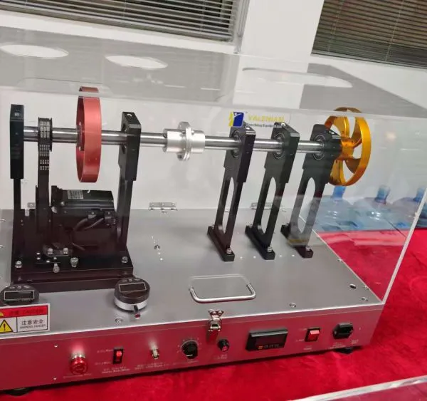
Two bearing blocks are installed in the driving part, and the other two bearing blocks are installed on the left and right sides of the driven part respectively. The bearing block installed in the center of the driven part is only used to learn the characteristics of faulty bearings; this bearing block is in an idle state with no bearing installed.
Leftmost: Inner ring faulty bearing;
Second from the left: Outer ring faulty bearing;
Rightmost: Cage faulty bearing;
Second from the right: Rolling element faulty bearing.
Loosen the screws on the bolts of the central bearing block, push the bearing to be tested in and fix it;
Measure after installing the acceleration sensor.
This design minimizes changes in boundary conditions, enabling immediate and accurate comparison between normal and faulty states, and avoids the process of completely disassembling and reassembling the rotor assembly to replace bearings.
From left to right:
Inner ring faulty bearing (0.55mm);
Outer ring faulty bearing (0.55mm);
Rolling element faulty bearing;
Cage faulty bearing.
The faulty bearing set includes the following 4 types of faulty bearings and 1 bearing block:
Inner ring faulty bearing
Identification: Marked with "I" in English on the bearing ring;
Fault characteristic: A 0.55 mm crack on the inner ring;
Fault frequency: 5.427 X.
Outer ring faulty bearing
Identification: Marked with "O" in English on the bearing ring;
Fault characteristic: A 0.55 mm crack on the outer ring;
Fault frequency: 3.572 X.
Cage faulty bearing (FBT-25)
Identification: Marked with "T" in English on the bearing ring;
Fault characteristic: The cage frequency (or fundamental rotation frequency) is the rotation speed of the rolling element cage assembly. This bearing simulates low-frequency modulated vibration phenomena by artificially creating faults on the cage;
Fault frequency: 0.397 X.
Bearing rolling element fault (FBB-25)
Ball faulty bearing, marked with the letter "B" on the bearing ring, with a 3mm spalling pit on the ball;
Fault characteristic frequency: 2x fault characteristic frequency: 4.644 X.
This component is used to simulate and analyze the vibration characteristics of bearings under different fault conditions, helping users learn fault diagnosis techniques;
Each faulty bearing has clear identification and characteristic frequencies, facilitating users to conduct accurate fault analysis and comparison.
The operation of the test bench is more flexible and convenient because the speed control knob and run/stop switch are installed on the front panel respectively, instead of directly using the keyboard function of the motor drive. This design makes the functional operation of the test bench more convenient, as variable resistance function control knobs are installed on the front panel, avoiding the inconvenience of using small keyboards.
Speed control knob: Installed on the front panel, allowing users to freely adjust the speed with simple and intuitive operation;
Run/stop switch: Installed on the front panel, enabling users to easily start or stop the test bench without relying on the motor drive keyboard;
Function control knobs: Adopting variable resistance design, they are installed on the front panel respectively to provide a more comfortable operating experience and avoid the inconvenience of using small keyboards.
An optical sensor is installed under the base plate to detect the shaft speed and obtain speed signals for synchronization. A speed signal of one pulse per revolution is output to the BNC terminal, which can be used as a synchronization signal for the signal analyzer. Therefore, the infrared speed sensor can be used for phase measurement without installation during balancing work. At the same time, this signal is also used to display RPM in real-time on the front panel. If the infrared sensor reflection tape attached to the surface of the motor shaft or coupling is removed, the speed cannot be detected.
Optical sensor: Installed under the base plate to detect shaft speed and generate speed signals;
BNC terminal output: A speed signal of one pulse per revolution can be used for synchronization of the signal analyzer;
Infrared speed sensor: Can perform phase measurement without installation during balancing work;
Real-time RPM display: Displays speed (RPM or Hz) in real-time on the front panel;
7-segment LED display: Continuously displays the instantaneous values of RPM and vertical weight.
When calibrating the alignment of the rotating shaft, dial indicators are installed on the front and rear feet of the motor base to study the measurement of movement on the left and right sides and learn the impact of misalignment on the equipment. In addition to providing accurate movement of the front and rear feet during centering work, the dial indicator can also be used to assist in quick centering and test misalignment conditions to accurately restore to the original state.
Installation position: Dial indicators are installed on the front and rear feet of the motor base;
Measurement function: Used to measure the movement of the left and right sides and study the impact of misalignment;
Centering assistance: Provides accurate movement information during centering work to assist in quick centering;
4.Restoration function: Tests misalignment conditions to help the equipment accurately restore to the original state.

Send Inquiry to This Supplier
You May Also Like
-
PT500mini Machinery Fault SimulatorUS$ 3799MOQ: 1 Combo
-
PT400 Vibration Demo Equipment Gear Fault SimulatorUS$ 3599MOQ: 1 Combo
-
PT650 Motor Fault Diagnosis SimulatorUS$ 3999MOQ: 1 Combo
-
PT560 Fluid Pump Valve Module Test BenchUS$ 3980MOQ: 1 Combo
-
PT580 Water Pump Test BenchUS$ 3699MOQ: 1 Combo
-
WFD1000 Wind-turbine SimulatorUS$ 2699MOQ: 1 Combo
-
PT500 Drivetrain Diagnostics SimulatorUS$ 2999MOQ: 1 Combo
-
PT5000 Turbine Sliding Bearing System Simulation Test BedUS$ 2599MOQ: 1 Combo
-
BTS100 Bearing Prognostic SimulatorUS$ 3800MOQ: 1 Combo
-
PT500pro Machine Vibration & Gearbox SimulatorUS$ 3980MOQ: 1 Combo

