








 Contact Platform Support
 Help Center
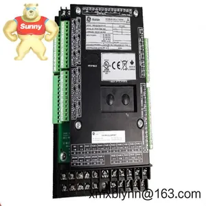
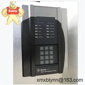
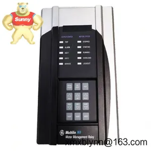
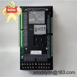
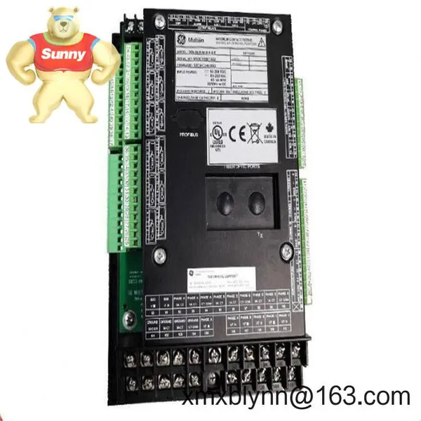
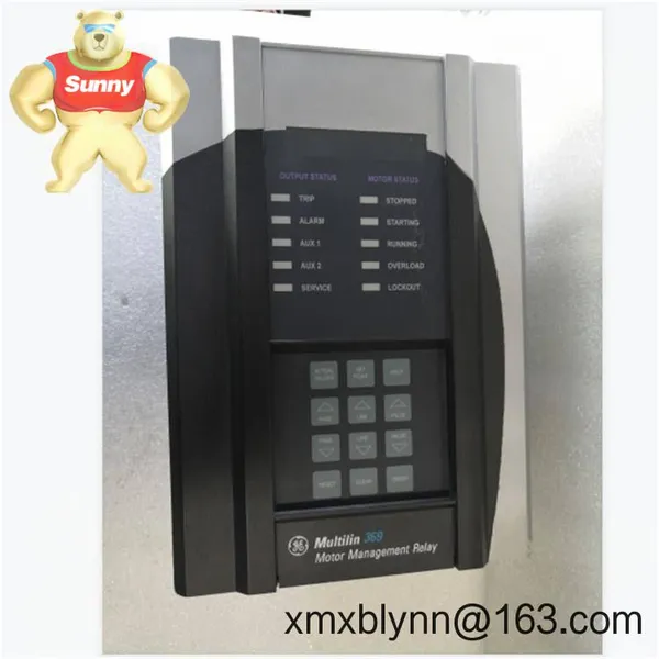
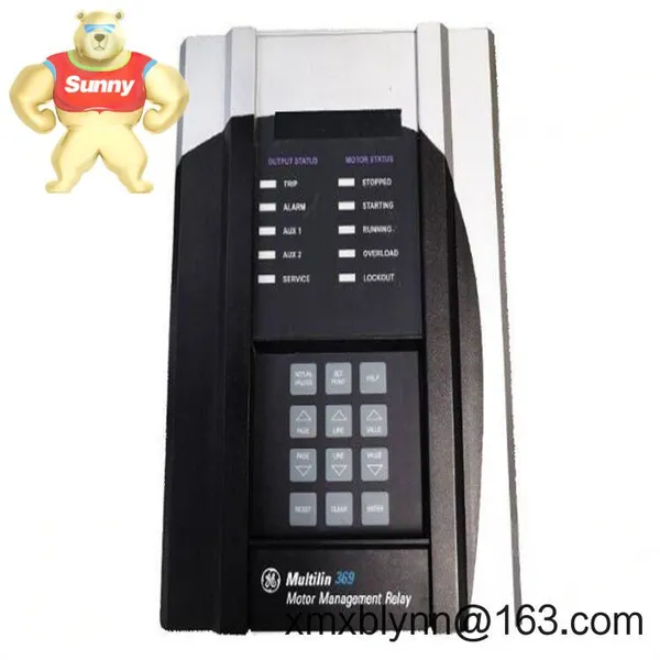
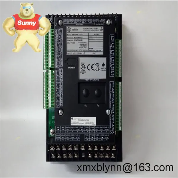
GE Multilin 369-HI-R-M-0-0-0-E Motor Management Relay – Protection, Monitoring, and Control for Critical Motors



Related Products
-
 GE 531X303MCPARG1 AC Power Board – Stable Control Power for Legacy GE Drive SystemsNegotiableMOQ: 1 Combo
 -
GE 531X303MCPBBG1 Main Control Power Board – Stable AC-to-DC Control Power for GE Drive and Excitation SystemsNegotiableMOQ: 1 Combo
-
GE 531X303MCPBDG1 – MCPB Control Board for AC/DC Drive PlatformsNegotiableMOQ: 1 Combo
-
GE 531X304IBDARG1 PC Basic Driver Card – Reliable Signal Interface for Legacy GE Drive PlatformsNegotiableMOQ: 1 Combo
-
GE 531X304IBDASG1 Inverter Bridge Driver Card – Reliable Gate Drive and Protection for GE Industrial DrivesNegotiableMOQ: 1 Combo
The GE Multilin 369 series is a workhorse motor management relay designed to protect and optimize medium and large induction motors in harsh industrial environments. The 369-HI-R-M-0-0-0-E build typically combines robust motor protection (thermal, jam/stall, ground fault) with temperature monitoring and enhanced metering. From my experience, it fits well in MCC buckets and switchgear retrofits where reliability, clear diagnostics, and straightforward wiring are priorities.
You might notice that sites choose the 369 for its stable thermal model and its flexible I/O. It seems to deliver a good balance between protection depth and day‑to‑day usability, especially when the team wants Modbus visibility in DCS/SCADA without adding extra hardware.
Key FeaturesComprehensive motor protection – Overload (thermal model), jam/stall, undercurrent, phase loss, phase unbalance, and ground fault to guard against common process and electrical faults.
Integrated temperature monitoring – The “R” option in this build appears to include RTD inputs for stator and bearing temperature; typically supports multiple Pt100 channels for early warning.
Advanced metering – The “M” option provides true RMS metering of currents and key electrical values, reducing the need for a separate feeder meter in many cases.
Flexible current inputs – Works with standard 1 A or 5 A secondary CTs; a separate ground CT can be used for sensitive ground fault protection.
Event records and diagnostics – Time‑stamped trips/alarms and trending help maintenance teams pinpoint root causes faster.
SCADA connectivity – RS‑485 Modbus RTU is commonly supported for remote monitoring, control, and data collection.
Rugged, plant-ready design – Built for panel or switchgear door mounting with a clear front interface for local operators.
Start control and permissives – Digital inputs/outputs allow permissive logic, interlocks, and start inhibit based on thermal capacity or temperature.
This relay is typically deployed on conveyor drives, pumps, fans, compressors, and mixers where both mechanical and electrical stresses can appear without much warning. In many cases, plants standardize on the 369 for their process‑critical motor feeders to keep trip logic and SCADA tags consistent across units.
Mining and aggregates – Crushers, conveyors, slurry pumps with jam/stall trip logic to prevent mechanical damage.
Oil & gas – Produced water pumps, cooling fans, and export pumps with RTD‑based thermal restraint.
Water & wastewater – Aeration blowers and high‑service pumps needing ground fault sensitivity and starts‑per‑hour limits.
Pulp & paper – Refiners and vacuum pumps, where unbalance and overload events are common during grade changes.
Metals and cement – High‑inertia drives benefiting from start supervision and thermal capacity tracking.
Power & utilities – Balance‑of‑plant motors with consistent Modbus telemetry back to DCS.
Reliable protection logic – The thermal model and jam/stall functions reduce nuisance trips while still reacting fast to real faults.
Retrofit‑friendly – Works with existing 1 A/5 A CTs and standard ground CTs; panel cutouts are straightforward in most MCC doors.
Lower total installed cost – With the “M” metering option, many users drop a separate feeder meter and wiring.
Maintenance visibility – Event logs and RTD trends help teams troubleshoot without dragging portable instruments to site.
Lifecycle support – Widely used platform with stable firmware and broad field experience; spares and know‑how are easy to source.
Mounting – Panel/door mount on a clean, vibration‑controlled surface; follow the 369 cutout drawing and maintain clearance for terminal access.
Power & grounding – Use a dedicated control power circuit with proper fusing; bond the relay ground to the panel ground bar to minimize noise.
CT/VT wiring – Observe CT polarity; never open‑circuit a live secondary. For sensitive ground fault, use a window (core‑balance) CT around phase conductors.
RTD and I/O – Route RTD leads separately from power; use shielded twisted pairs and land shields at one end to reduce interference.
Ventilation – Keep ambient within spec; provide cabinet ventilation if mounting alongside heat‑generating drives or soft starters.
Configuration – Commission with conservative protection pickups, then tune using event logs and thermal capacity feedback after a few weeks of operation.
Routine care – Annually verify trip circuits, clean terminals, back up settings files, and update firmware when validated for your site standard.
Spare strategy – For critical lines, many sites hold 1:10 spares, plus one ground CT and a set of pre‑terminated RTD harnesses.
Core‑balance ground CT sized to your feeder cables for sensitive earth‑fault detection.
Pt100 RTDs for stator slots and bearing housings; three‑wire configuration is typical for accuracy.
RS‑485 to Ethernet gateway (if your SCADA is Ethernet‑only) with Modbus pass‑through.
Miniature control power breaker and surge suppressors for the control supply circuit.
CE compliant for EMC and Low Voltage directives (model dependent and region specific).
UL/cUL listing for industrial control equipment is commonly available on 369 series builds.
RoHS alignment where applicable; consult the exact build code for material declaration.
Manufacturer’s warranty: typically 2 years from shipment when installed per the manual.

Send Inquiry to This Supplier



You May Also Like
-
GE 531X305NTBANG1 Terminal Board – Reliable Field I/O Termination for GE Drive SystemsNegotiableMOQ: 1 Combo
-
GE 531X305NTBAPG1 – NTBA Terminal Board for Field I/O Termination in Legacy GE Drives and Control SystemsNegotiableMOQ: 1 Combo
-
GE 531X307LTBAHG1 LAN Terminal Board – Reliable Field I/O and LAN Termination for Legacy GE Drive SystemsNegotiableMOQ: 1 Combo
-
GE 531X307LTBAJG1 LAN Terminal Board – Reliable Field Wiring Interface for GE Drive NetworksNegotiableMOQ: 1 Combo
-
GE Multilin 750-P1-G1-S1-HI-A20-G – Feeder Protection Relay for Reliable MV/LV DistributionNegotiableMOQ: 1 Combo
-
GE PAC8000 8521-HC-MT – HART Maintenance Access for Remote Field I/ONegotiableMOQ: 1 Combo
-
GE LV5F30-NF – Low-voltage AC Drive for Reliable Motor Control in Pumps, Fans, and ConveyorsNegotiableMOQ: 1 Combo
-
GE Multilin 369-HI-0-M-0-0 – Motor Management Relay for Reliable Three‑Phase Motor ProtectionNegotiableMOQ: 1 Combo
-
GE Multilin 369-HI-0-M-0-E-0 Motor Management Relay – Intelligent Protection and Monitoring for Critical MotorsNegotiableMOQ: 1 Combo
-
GE Multilin 369-HI-0-M-0-0-0 – Motor Management Relay for Reliable AC Motor ProtectionNegotiableMOQ: 1 Combo


