

Home > Electrical & Electronics > Electrical Control System > GE ENERGY HYDRAN H201Ci-1 Single-Channel Controller
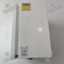
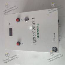
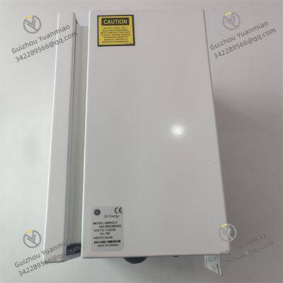
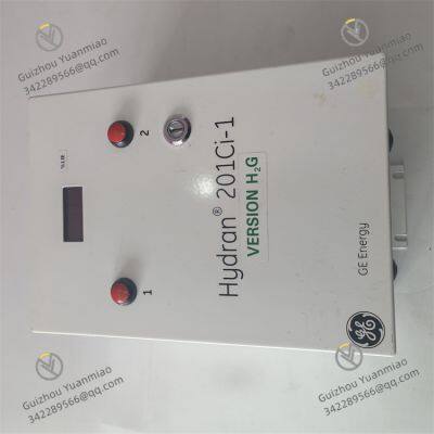
GE ENERGY HYDRAN H201Ci-1 Single-Channel Controller
Negotiable
MOQ: 1 Piece (Price negotiable depending on order volume and customization)
Key Specifications
Get Latest Price
Material:
Other, Global universal model
Condition:
Other, Global universal model
Task:
Other, Global universal model
Payment & Shipping
Payment Methods:
Port of Shipment:
China
Delivery Detail:
Delivery time depends on order quantity.
Related Products
-
 GE H201Ti Dissolved Gas Analysis (DGA) MonitorNegotiableMOQ: 1 Piece
 -
GE IS420PUAAH1A Universal Input/Output ModuleNegotiableMOQ: 1 Piece
-
GE IS220UCSAH1AK PAMC Acoustic Monitor ProcessorNegotiableMOQ: 1 Piece
-
GE D20 EME 2400-21004 Substation ControllerNegotiableMOQ: 1 Piece
-
GE D20 EME210BASE-T Ethernet ModuleNegotiableMOQ: 1 Piece
Material
Other, Global universal model
Condition
Other, Global universal model
Task
Other, Global universal model
Mathematical Model
Other, Global universal model
Signal
Other, Global universal model
Customized
Non-Customized
Structure
Other, Global universal model
Operating Temperature
-30℃~60℃
Measurement accuracy
±0.5℃
Storage Temperature
-40℃~85℃
I. Product Overview
II. Technical Specifications and Performance
Monitoring Parameters and Accuracy
2. Electrical and Communication Characteristics
3. Environmental and Protection Performance
4. Diagnosis and Alarm Functions
III. Installation and Operation & Maintenance
Installation Specifications
(1) Installation Method (Portable External Connection Type)
(2) Installation Precautions
2. Daily Operation & Maintenance
(1) Regular Inspection (Once a Month)
(2) Regular Calibration (Once a Year)
(3) Troubleshooting

Send Inquiry to This Supplier

* Email
Want the best price?
Post an RFQ now!

1Yr
Business Type
Trading Company
Year Established
2014
Factory Size
1,000-3,000 square meters
Product Certifications
SA8000
You May Also Like
-
GE D20 EME 27-APR-13 Input/Output ModuleNegotiableMOQ: 1 Piece
-
GE WESCOM D200 VME 0517-01230D Versatile And Reliable ModuleNegotiableMOQ: 1 Piece
-
GE WESDAC D20ME 18-MAR-13 Control Output ModuleNegotiableMOQ: 1 Piece
-
GE WES5120 2340-21006 Field Controller Master Unit ModuleNegotiableMOQ: 1 Piece
-
GE WES5120 2340-21004 Field Controller Master Unit ModuleNegotiableMOQ: 1 Piece
-
GE WEA13-13 2508-21001 Substation ControllerNegotiableMOQ: 1 Piece
-
GE IS200TSVCH1AED Servo I/O Terminal BoardNegotiableMOQ: 1 Piece
-
GE IS200TTURH1CCC S1DF00Z Turbine Terminal BoardNegotiableMOQ: 1 Piece
-
GE IS200TSVCH1ADC S1CX01H Servo I/O Terminal BoardNegotiableMOQ: 1 Piece
-
GE IC698CHS017B RX7i WALL (REAR) MOUNT RACKNegotiableMOQ: 1 Piece


