

Home > Electrical & Electronics > Electrical Control System > Foxboro FCM2F2 P0914YZ Optical Fiber Communication Extender
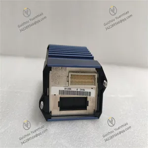
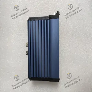
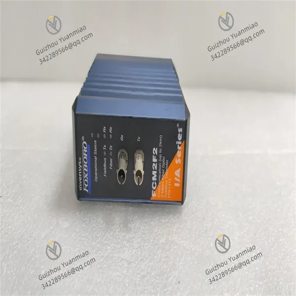
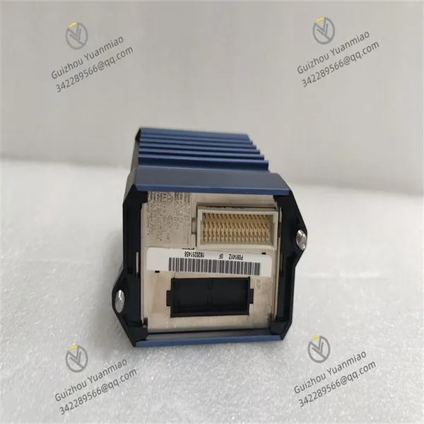
Foxboro FCM2F2 P0914YZ Optical Fiber Communication Extender


Negotiable
MOQ: 1 Piece (Price negotiable depending on order volume and customization)
Key Specifications
Get Latest Price
Material:
Other, Global universal model
Condition:
Other, Global universal model
Task:
Other, Global universal model
Payment & Shipping
Payment Methods:
Port of Shipment:
China
Delivery Detail:
Delivery time depends on order quantity.
Related Products
-
 Foxboro FEM100 P0973CA Fieldbus Expansion ModuleNegotiableMOQ: 1 Piece
 -
Foxboro FBM241 P0914TG 8-Channel Voltage Monitoring ModuleNegotiableMOQ: 1 Piece
-
Foxboro FBM242 P0916TA Discrete Output Interface ModuleNegotiableMOQ: 1 Piece
-
Foxboro FBM230 P0926GU Switch Quantity I/O ModuleNegotiableMOQ: 1 Piece
-
Foxboro FBM232 P0926GW Ethernet Communication ModuleNegotiableMOQ: 1 Piece
Material
Other, Global universal model
Condition
Other, Global universal model
Task
Other, Global universal model
Mathematical Model
Other, Global universal model
Signal
Other, Global universal model
Customized
Non-Customized
Structure
Other, Global universal model
Operating temperature
-20°C to +70°C
Storage temperature
-40°C to +70°C
Humidity
5% to 95% (non-condensing)

Send Inquiry to This Supplier


Business Type
Trading Company
Year Established
2014
Factory Size
1,000-3,000 square meters
Product Certifications
SA8000
You May Also Like
-
Foxboro FBM233 P0926GX Analog Input ModuleNegotiableMOQ: 1 Piece
-
Foxboro FBM237 RH914XS Output ModuleNegotiableMOQ: 1 Piece
-
Foxboro FBM240 P0917GZ Fieldbus ModuleNegotiableMOQ: 1 Piece
-
Foxboro FCP280 RH924YA Field Control ProcessorNegotiableMOQ: 1 Piece
-
Foxboro FCP270 P0917YZ Field Control ProcessorNegotiableMOQ: 1 Piece
-
FOXBORO FBM216b P0927AJ Communication Redundant Input Interface ModuleNegotiableMOQ: 1 Piece
-
FOXBORO FBM227 P0927AC Control System ModuleNegotiableMOQ: 1 Piece
-
FBM201D P0922YK Analog Input ModuleNegotiableMOQ: 1 Piece
-
P0904HN FOXBORO Power ModuleNegotiableMOQ: 1 Piece
-
FBM01 FOXBORO Input Interface ModuleNegotiableMOQ: 1 Piece


