Home > Electrical & Electronics > Electrical Control System > MOTOROLA MVME162-530A Embedded CPU Board

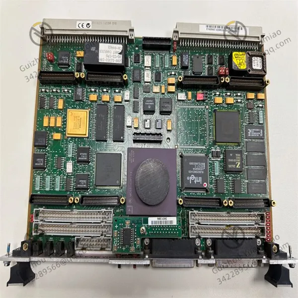
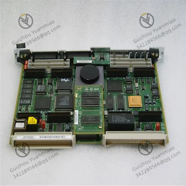
MOTOROLA MVME162-530A Embedded CPU Board
MOTOROLA MVME162-530A Embedded CPU Board photo-1
MOTOROLA MVME162-530A Embedded CPU Board photo-2
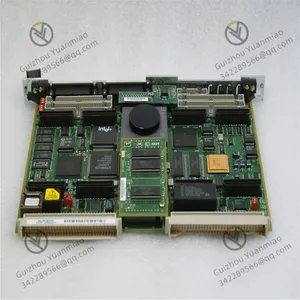
MOTOROLA MVME162-530A Embedded CPU Board photo-3
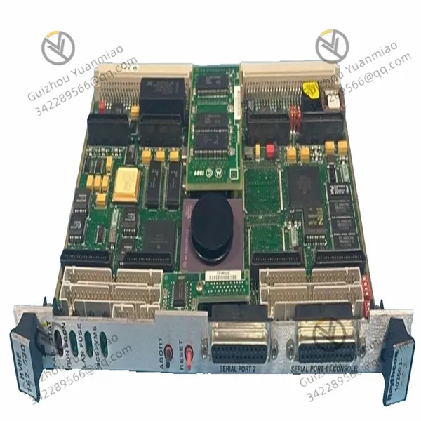
Negotiable MOQ: 1 Piece (Price negotiable depending on order volume and customization)
Key Specifications
Get Latest Price
Material:
Other
Certification:
Other
Function:
Other

Payment & Shipping
Payment Methods:
Port of Shipment:
China
Delivery Detail:
Delivery time depends on order quantity.
Material Other
Certification Other
Function Other
Condition Other
Task Other
Mathematical Model Other
Signal Other
Customized Other
Structure Other
MOTOROLA MVME162-530A embedded CPU board

MVME162-520A—01


I. Hardware Architecture and Collaborative Principles of Core Components1. Processor Module: Arithmetic and Control HubProcessor Selection and Architecture
  • Equipped with a PowerPC 603e processor (typically 200MHz or higher), based on a 32-bit RISC (Reduced Instruction Set Computing) architecture. This architecture achieves efficient instruction processing through a simplified instruction set and optimized pipeline design (e.g., 5-stage pipeline: fetch, decode, execute, store, write-back), with integer computing performance exceeding 130 MIPS and floating-point capability reaching 60 MFLOPS (compliant with IEEE 754 standards).

Operational Logic Workflow
  • The processor reads instructions from memory or cache, parses them into micro-operations via an instruction decoder, executes calculations (e.g., addition/subtraction/multiplication/division, logical judgments) through an Arithmetic Logic Unit (ALU), and temporarily stores results in registers or writes them back to memory. Meanwhile, the Memory Management Unit (MMU) enables virtual memory mapping and memory protection, ensuring program space isolation in multitask systems.

Cache System Optimization
  • Integrates 16KB instruction cache + 16KB data cache, using high-speed SRAM to store frequently accessed data/instructions. When the processor requests data, it first queries the cache: if hit, data is read directly (nanosecond-level latency); if missed, data is read from main memory (SDRAM) and the cache is updated, reducing memory access latency (SDRAM latency ~50-70ns).

2. Memory Subsystem: Data Storage and InteractionMain Memory (SDRAM)
  • Standard  64MB/128MB SDRAM (expandable to 256MB), supporting ECC (Error Correction Code). During operation, the processor loads running programs and data into SDRAM, communicating via a 32-bit data bus with transfer rates limited by the bus frequency (e.g., VME bus up to 40MB/s). ECC detects and corrects single-bit errors through parity codes, ensuring data reliability in industrial environments.

Boot Memory (Flash)
  • 8MB Flash stores  boot programs (e.g., BIOS), OS kernels (e.g., VxWorks, Linux), and initialization configurations. After power-on, the processor first reads the boot program from Flash, completes Power-On Self-Test (POST), and then loads the OS into SDRAM for execution.

Backup Memory (SRAM)
  • 512KB SRAM with lithium battery backup stores real-time data (e.g., sensor parameters, control commands) and system configurations. During power outages, the battery maintains SRAM power to prevent data loss, ensuring key states are restored after reboot.

3. Bus and Interfaces: Data Transmission and External CommunicationCore Functions of VME Bus
  • As the main bus interface, it supports A32/D32 (32-bit address/data) and A24/D16 modes, with a maximum transfer rate of 40MB/s. The MVME162-530A can act as a bus master (initiating data transfers, e.g., reading from slave devices) or a slave (responding to master requests). The bus arbitration mechanism ensures orderly bus access via handshake signals (e.g., BBSY, BREQ, BGNT) in multiprocessor systems.

Logic of Standard Communication Interfaces
  • RS-232/RS-422 Serial Ports: Convert parallel data to serial streams via UART controllers, supporting up to 921.6kbps baud rate, compatible with industrial protocols (e.g., Modbus, CANopen) for connecting sensors, actuators, or host computers.

  • Ethernet Interface: Integrates 10/100Mbps physical layer chips (e.g., RTL8139), implements TCP/IP/UDP protocol stacks via MAC layer controllers, enabling network configuration, remote monitoring, or data upload (e.g., sending device status to the cloud).

  • USB 1.1 Interface: Connects debugging devices (e.g., USB-to-serial adapters) or external storage, processing low-speed (1.5Mbps) or full-speed (12Mbps) data via USB controllers.

Expansion Interfaces and Functional Modules
  • Four IndustryPack® slots support dedicated modules (e.g., A/D converters, D/A outputs), with the board communicating via local buses (e.g., PCI or custom buses) for function expansion. Optional SCSI interfaces manage storage devices (e.g., HDDs) via SCSI controllers at 5MB/s.

  • MVME162PA-344E—02

II. System Boot and Operation Principles1. Power-On Initialization ProcessHardware Self-Test (POST)
  • After power-up, the processor reads the boot program from Flash, sequentially checks hardware (memory, cache, interface chips, etc.), and feedbacks status via indicators (e.g., power LED on, ready LED blinking).

OS Loading
  • After passing POST, the boot program loads the OS kernel (e.g., VxWorks) from Flash into SDRAM, initializes system resources (e.g., interrupt vector tables, device drivers). The OS then mounts the file system (e.g., root file system in Flash) and enters the user interface (CLI or GUI).

2. Real-Time Task Processing MechanismsMultitask Scheduling
  • Based on RTOS, tasks are managed via priority preemptive scheduling. Each task has independent stack space and context; when a high-priority task is ready, the system saves the current task state (register values, program counter) and switches to the new task, with switching latency typically

Interrupt Handling Flow
  • External devices (e.g., sensors) send requests via interrupt lines, prompting the processor to pause the current task, jump to the Interrupt Service Routine (ISR) for event handling (e.g., reading sensor data), and resume the original task after completion. Interrupt priorities are configurable, with critical interrupts (e.g., emergency faults) able to preempt low-priority tasks for system stability.

3. Industrial-Grade Reliability Design PrinciplesEnvironmental Adaptability Technologies
  • Wide Temperature Design: Using industrial-grade components (e.g., wide-temperature capacitors, resistors) and optimized PCB layout, the board operates stably at -20°C to +60°C (standard) or -40°C to +85°C (wide-temperature), preventing component performance drift due to temperature changes.

  • Vibration/Shock Resistance: Rigid PCB design and bottom soldering/adhesive fixation of key chips reduce physical damage under vibration (5-2000Hz, 1.5g) or shock (30g, 11ms), complying with MIL-STD-810F.

Power and Fault Tolerance Mechanisms
  • Power Management: +5V DC supply with built-in filtering to suppress ripple, supporting power redundancy (e.g., dual-power automatic switching) to prevent system crashes during outages.

  • Watchdog Timer: An independent hardware circuit periodically receives processor signals; if the system freezes (e.g., program runaway), the timer forces a processor reboot for automatic recovery.


III. Operational Logic in Typical Application Scenarios1. Industrial Automation ControlData Acquisition and Processing
  • Access A/D modules via IndustryPack® slots to collect analog signals from sensors (e.g., temperature, pressure), convert them to digital values for processor computation (e.g., PID control algorithms), and output results to actuators (e.g., valves, motors) via D/A modules.

Multi-Device Collaborative Control
  • As a VME bus master, coordinate slave devices (e.g., I/O modules, communication cards), send control commands via the bus, and receive feedback to achieve high-precision motion control for multi-axis robots or CNC machines.

2. Aerospace Data ProcessingReal-Time Signal Processing
  • Receive sensor data (e.g., attitude, speed) from flight simulators, quickly solve motion equations via the processor, and generate analog signals to drive display devices, ensuring real-time and accurate simulation scenarios.

Redundancy and Fault Tolerance
  • In avionics, implement hot backup of multi-board cards (e.g., primary/backup CPU boards) and data verification (ECC, CRC) to reduce single-point failure risks, meeting aviation's high-reliability requirements.

  • MVME162-410—01

IV. Technical Evolution Principles Compared with Predecessors
Compared with previous MC68040-based boards (e.g., MVME162P-244L), MVME162-530A's performance improvements stem from:


  • Instruction Set and Architecture Upgrade: Shift from CISC to RISC, reducing per-instruction cycles and combining with pipeline technology to boost integer performance by 8-10x (e.g., 220 MIPS vs. 16.5 MIPS).

  • Memory Subsystem Optimization: SDRAM replaces DRAM, capacity expands from 8MB to 256MB with ECC for reliability, while cache capacity doubles to reduce memory latency.

  • Bus and Interface Standardization: Integrated 10/100Mbps Ethernet replaces optional 10BASE-T, supporting higher-speed network communication for industrial IoT needs.


V. Principle Analysis of Technical Limitations
  • VME Bus Bandwidth Bottleneck: The maximum 40MB/s rate is limited by bus protocols (e.g., asynchronous transmission, arbitration), potentially causing data congestion for real-time video streams or large data transfers (requires external high-speed interface expansion).

  • Volume vs. Integration Trade-off: The 6U form factor, designed for industrial heat dissipation and anti-interference, occupies significant space. In high-density embedded systems, modular design (e.g., splitting functions into daughter cards) is needed to ease space constraints.

  • Software Ecosystem Compatibility: Dependence on traditional RTOS (e.g., VxWorks) and limited support for new Linux drivers arise from differences between PowerPC and mainstream ARM architectures, requiring custom driver development.


Conclusion
The working principle of MVME162-530A essentially achieves real-time data processing and control through collaboration among the PowerPC processor, memory subsystem, bus interfaces, and industrial-grade hardware. Its core advantages lie in the efficient computation of RISC architecture, reliability designs like ECC and watchdog, and multi-device collaboration via VME bus, making it suitable for harsh industrial and aerospace scenarios demanding stability and real-time performance. Despite bandwidth and volume limitations, its mature technical architecture remains irreplaceable in specific fields.


Product Tags: MVME162-530A

Send Inquiry to This Supplier

* Message
0/5000

Want the best price? Post an RFQ now!
Verified Business License
Business Type
Trading Company
Year Established
2014
Factory Size
1,000-3,000 square meters
Product Certifications
SA8000