








 Contact Platform Support
 Help Center
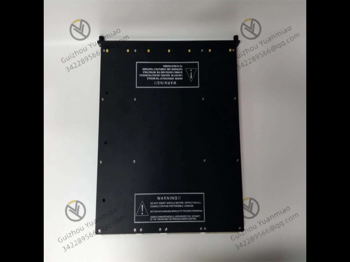
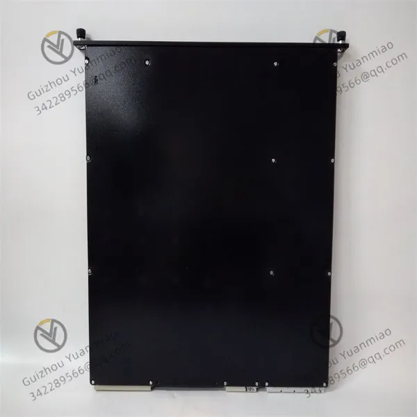
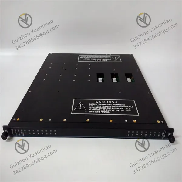
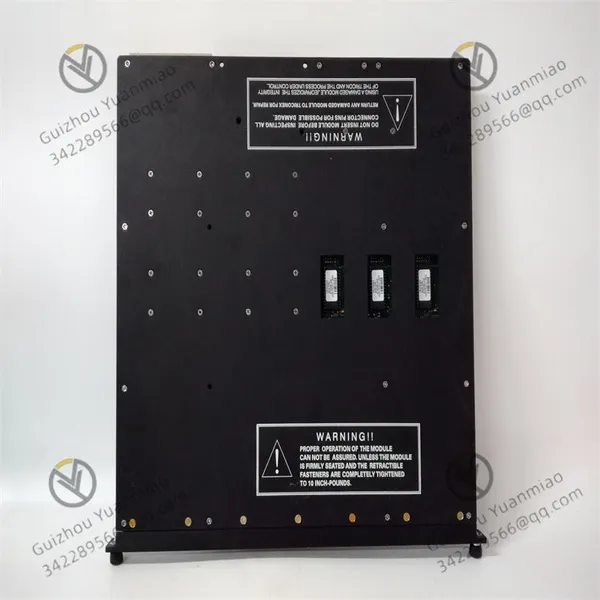
TRICONEX 3604E Digital Output Module



Related Products
-
 TRICONEX 3625C1 Digital Output ModuleNegotiableMOQ: 1 Piece
 -
TRICONEX 3700A Analog Input ModuleNegotiableMOQ: 1 Piece
-
TRICONEX 3636R Relay Output ModuleNegotiableMOQ: 1 Piece
-
TRICONEX 3636T Digital Relay Output ModuleNegotiableMOQ: 1 Piece
-
TRICONEX 3700A Analog Input ModuleNegotiableMOQ: 1 Piece
TRICONEX 3604E Digital output module
Basic parameters:
Working voltage: 24VDC.
Voltage range: 22-45VDC.
Output signal quantity: 16 channels.
Weight: 3.65kg.
Dimensions: 49x45.3x6.8cm.
Working principle
I. Signal Processing Mechanism of Three Modular Redundancy (TMR) Architecture
Input signal reception and splicing
The module receives digital control signals (such as on/off commands) from the main processor of the TRICON controller. The signals first enter three independent circuit channels (channels A, B, and C) inside the module. Each channel independently processes the signals, forming a triple redundant path.
Example: When the controller sends the digital signal of "Open the valve", the signal is simultaneously transmitted to three channels to avoid signal loss caused by a single point of failure.
Triple signal voting and output
After each channel processes the input signal, A vote is made through a quadruple output circuit: three groups of signals (outputs from channels A, B, and C) are voted on by hardware logic (majority voting principle, that is, 2/3 voting), and finally a unified output signal is generated.
If one of the channels malfunctions (such as an abnormal signal), the signals of the other two normal channels can still generate the correct output through voting, ensuring the reliability of the control instructions.
Ii. Electrical Conversion and Output Control of Digital Signals
Signal level conversion
The module internally converts the digital logic signals of the controller (such as 5V TTL level) into 24VDC signals suitable for driving field equipment, and the driving capacity meets the load requirements such as solenoid valves and relays (the maximum output current of a single channel is usually 0.5A to 1A).
Output channel control mechanism
The 16 output channels are independently controllable. Each channel is electrically isolated through a solid-state relay (SSR) or transistor switch to prevent the impact of load side faults on the module.
When controlling a certain solenoid valve, the module outputs a 24VDC signal, which is connected to the solenoid valve coil through a solid-state relay to achieve the valve opening and closing action. At the same time, electrical isolation ensures that the strong current circuit does not interfere with the internal circuit of the module.
Iii. Voltage Backloop Diagnosis and Fault Monitoring
Output status verification mechanism
The module is equipped with a built-in voltage loopback circuit for real-time monitoring of each output channel:
When the output channel is commanded as "high level" (24VDC), the loopback circuit detects whether there is actually a 24VDC voltage at the output point. If the detected voltage does not match the command status (such as an open load or a blown fuse), a "load/fuse alarm" will be triggered and displayed through an indicator light.
If the output channel is commanded as "low level", the loopback circuit verifies whether the output point is at a low level to prevent channel adhesion (such as continuous high level output due to transistor breakdown).
Continuous self-diagnosis and fault isolation
The module continuously self-diagnoses the internal circuits (such as power supply, processor, and output drive circuits). Once A channel fault is detected (such as abnormal A/D conversion in a certain channel or logic circuit errors), it immediately marks the channel as a "fault" and sends diagnostic information to the controller through the backplane.
Key features: The failure of a single channel will not affect the operation of other channels. The module continues to output through the remaining normal channels, achieving "fault tolerance". If multiple channels fail (such as exceeding the redundant design range), the module will enter a safe state (such as output locking or setting to a preset value) to prevent misoperation.
Iv. Hot Standby and System Integration Design
The hot standby function has been realized
When the module supports hot standby configuration, it is connected to the external terminal board (ETP) through a dedicated cable, and the main module and the standby module synchronously output the status in real time. When the main module fails, the backup module automatically takes over the control to ensure the uninterrupted operation of the on-site equipment (the switching time is usually in the millisecond range).
Collaborative work with the TRICON system
The module communicates with the controller through the TRICON backplane, receiving control instructions while feeding back real-time status (such as output values and fault information). The controller is based on a three-redundancy architecture and re-votes on the triple output signals of the module to form a "system-module" dual redundancy, further enhancing security.
V. Safety Output Strategy and Failure Protection
Fail-Safe design
When the module detects irreparable serious faults (such as continuous abnormal power supply, core circuit damage), or communication interruption with the controller, it can set the output to the "safe state" according to the preset configuration (such as all outputs being low level, causing the solenoid valve to lose power and close), to prevent the on-site equipment from losing control due to module failure. Comply with the SIL level requirements of the Safety Instrumented System (SIS).

Send Inquiry to This Supplier


You May Also Like
-
TRICONEX 3704E Analog Input ModuleNegotiableMOQ: 1 Piece
-
TRICONEX 3805E High-speed Frequency/pulse Input ModuleNegotiableMOQ: 1 Piece
-
TRICONEX 3806E Analog Output ModuleNegotiableMOQ: 1 Piece
-
TRICONEX 4119A Mainframe Processor ModuleNegotiableMOQ: 1 Piece
-
TRICONEX 4351B Communication ModuleNegotiableMOQ: 1 Piece
-
TRICONEX 8310N2 Digital Output ModuleNegotiableMOQ: 1 Piece
-
TRICONEX 8311N Power ModuleNegotiableMOQ: 1 Piece
-
TRICONEX 9563-810 Digital Input ModuleNegotiableMOQ: 1 Piece
-
TRICONEX 9566-810 Digital Output ModuleNegotiableMOQ: 1 Piece
-
TRICONEX 9662-810 Analog Output ModuleNegotiableMOQ: 1 Piece


