Home > Electrical & Electronics > Electrical Control System > ABB PFTL101A-2.0kN 3BSE004172R1 Load Cell

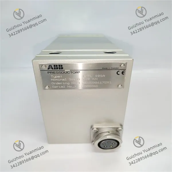
ABB PFTL101A-2.0kN 3BSE004172R1 Load Cell

ABB PFTL101A-2.0kN 3BSE004172R1 Load Cell photo-1
ABB PFTL101A-2.0kN 3BSE004172R1 Load Cell photo-2

Negotiable MOQ: 1 Piece (Price negotiable depending on order volume and customization)
Key Specifications
Get Latest Price
Material:
Other, Global universal model
Condition:
Other, Global universal model
Task:
Other, Global universal model

Payment & Shipping
Payment Methods:
Port of Shipment:
China
Delivery Detail:
Delivery time depends on order quantity.
Material Other, Global universal model
Condition Other, Global universal model
Task Other, Global universal model
Mathematical Model Other, Global universal model
Signal Other, Global universal model
Customized Non-Customized
Structure Other, Global universal model
Basic Information
  • Model: PFTL101A, belonging to ABB's specific sensor series.

  • Rated Load: 2.0kN, indicating the maximum force value the sensor can accurately measure. It is suitable for application scenarios requiring medium-sized tension measurement.

  • Product Number: 3BSE004172R1, serving as the unique identifier for distinguishing different versions and specifications.

Working Principle
Based on ABB's renowned Calibrator® technology, it utilizes the magnetoelastic effect for measurement. When subjected to mechanical force, the magnetic properties of the internal materials of the sensor change due to the applied mechanical force, and the sensor generates measurement signals according to the changes in the magnetic field. Since the signal does not depend on physical movement or deformation, this sensor combines sensitivity with extraordinary tolerance to overload, and has almost no built-in limit on the number of load cycles.
Application Scope
Suitable for various industrial applications, such as metal processing, textiles, printing, packaging, cable manufacturing, and other industries. It plays a role in links requiring precise control of material tension or force measurement, helping to improve the stability of production lines and product quality.
Product Features
  • High Precision: Provides accurate force measurement results to ensure precise control and monitoring in industrial processes.

  • Robust and Durable: Adopts a durable design, capable of withstanding harsh industrial environments, and delivering stable and consistent performance and reliability over long periods.

  • Compact and Universal: Features a compact design, occupying minimal space, facilitating integration into different systems and equipment, and offering high versatility and flexibility.

Technical Specifications
  • Country of Origin: Sweden.

  • Gross Weight: 10.5kg.

  • Product Type: Automation control component.

  • Customs Tariff Number: 84733080.

  • Connection Components: Can be equipped with cables of different lengths with male plug connectors, such as 15m, 30m, 50m, etc., with part numbers 3BSE018741R15, 3BSE018741R30, and 3BSE018741R50 respectively.

PFTL101A-2

PFTL101A-2

What precautions should be taken when installing ABB PFTL101A-2.0kN 3BSE004172R1I. Mechanical Installation Requirements
  1. Installation Position and Direction
  • Alignment of Force Direction: Ensure that the tension load is evenly applied along the axial direction of the sensor (perpendicular to the axis of the elastomer), avoiding eccentric loads or lateral forces (lateral forces will cause measurement errors ≥0.5% FSO).
    ▶ Example: Use a special mounting bracket during installation to ensure that the force action line coincides with the central axis of the sensor.

  • Avoid Vibration Sources: Keep away from strong vibration equipment such as large motors and punching machines. If unavoidable, install a shock-absorbing base (such as a rubber buffer pad). The vibration frequency should be controlled within 10~2000Hz, and the amplitude ≤0.5mm.

  • Space Reservation: Reserve ≥10cm of operating space around the sensor to facilitate cable connection and subsequent maintenance, and avoid mechanical interference with other equipment.

  • Installation Strength and Tightening
    • Bolt Specifications: Use M8~M10 high-strength bolts (recommended above grade 8.8). The tightening torque should comply with the manual requirements (typically 15~25N・m) to avoid elastomer deformation due to over-tightening or loosening due to under-tightening.

    • Mechanical Limitation: If the application scenario has an overload risk (such as emergency stop), install a mechanical stop device (such as a limit block) near the sensor to ensure that the load does not exceed 150% of the rated value (i.e., 3.0kN).

  • Coaxiality and Parallelism
    • Coaxiality of the Transmission System: If used for roller tension measurement, ensure that the parallelism between the roller axis and the sensor installation surface is ≤0.1mm/m to avoid uneven force caused by skewing.

    • Flatness of the Installation Base Surface: The roughness of the installation surface should be ≤Ra1.6μm, and the flatness ≤0.05mm. Otherwise, install metal shims (such as stainless steel shims) for leveling.

    II. Electrical Connection Specifications
    1. Cable Selection and Laying
    • Signal Cable: Use twisted-pair shielded cable (cross-sectional area ≥0.5mm²). The shield layer should be grounded at a single end (it is recommended to ground it at the controller end) to avoid electromagnetic interference (EMI).
      ▶ Transmission Distance: Analog signal (4-20mA) ≤500m, digital signal (RS485) ≤1200m. For ultra-long distances, install a signal repeater.

    • Power Cable: If the sensor requires an external power supply (such as 24VDC), the power cable and signal cable should be laid separately with a spacing ≥10cm to prevent power noise interference.

  • Interface and Polarity
    • Wiring Terminal Definition:

      Terminal Mark Function Wiring Requirements
      +Vcc Positive power supply Connect to 24VDC±10%, and a 100μF/35V filter capacitor should be connected in parallel
      GND Power ground Common ground with the system ground to avoid ground loops
      SIG+ Positive signal Positive terminal for analog (such as 4-20mA) or digital signal output
      SIG- Negative signal Negative terminal for analog or digital signal output
    • Polarity Check: Measure the power supply voltage with a multimeter before wiring to ensure correct positive and negative poles. Reverse connection may damage the internal circuit.

  • Grounding and Anti-Interference
    • Ground Resistance: The system ground resistance should be ≤4Ω. If the site is in a high-frequency interference environment (such as near a frequency converter), independent grounding is recommended, with a spacing ≥5m from the power grounding.

    • Surge Protection: Install a surge protector (SPD) at the signal input end, especially suitable for outdoor or thunderstorm-prone areas, to prevent transient overvoltage from damaging the sensor.

    Product Tags: PFTL101A-2.0kN , 3BSE004172R1 , Load cell

    Send Inquiry to This Supplier

    * Message
    0/5000

    Want the best price? Post an RFQ now!
    Verified Business License
    Business Type
    Trading Company
    Year Established
    2014
    Factory Size
    1,000-3,000 square meters
    Product Certifications
    SA8000