








 Contact Platform Support
 Help Center
Adv551-p50



Related Products
-
 Mt300-d00-u1-p1-h Gauge Pressure Gauge, YokogawaNegotiableMOQ: 0 Unit
 -
Mt300-g01-u1-p1-h Digital Pressure Gauge, YokogawaNegotiableMOQ: 0 Unit
-
Mt300-g03-u1-p1-h Gauge Pressure Gauge, YokogawaNegotiableMOQ: 0 Unit
-
Supply Mgh0015w Intelligent Flowmeter OvalNegotiableMOQ: 0 Unit
-
Supply of Hygienic Mgh0032k Electromagnetic Flowmeter, Intelligent Oval ObaraNegotiableMOQ: 0 Unit
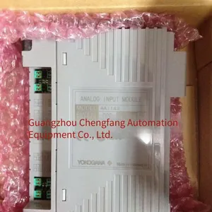
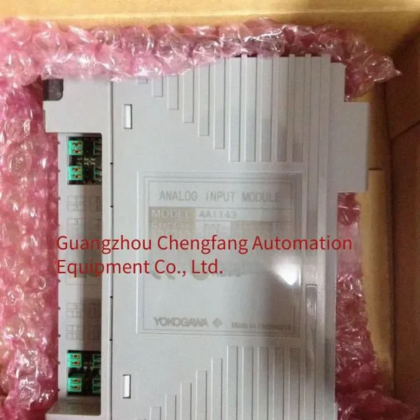
Yokogawa, JapanADV551Digital output module model:
ADV551-P50 ADV551-P53 ADV551-P60 ADV551-P63 ADV551-PE0 ADV551-PE3 ADV551-PF0 ADV551-PF3
ADV551-P50/D5A00 ADV551-P53/D5A00 ADV551-P60/D5A00 ADV551-P63/D5A00 ADV551-PE0/D5A00 ADV551-PE3/D5A00 ADV551-PF0/D5A00 ADV551-PF3/D5A00
ADV551-P50/D5S00 ADV551-P53/D5S00 ADV551-P60/D5S00 ADV551-P63/D5S00 ADV551-PE0/D5S00 ADV551-PE3/D5S00 ADV551-PF0/D5S00 ADV551-PF3/D5S00
ADV551-P50/D5S10 ADV551-P53/D5S10 ADV551-P60/D5S10 ADV551-P63/D5S10 ADV551-PE0/D5S10ADV551-PE3/D5S10 ADV551-PF0/D5S10 ADV551-PF3/D5S10
ADV551-P50/D5D00 ADV551-P53/D5D00 ADV551-P60/D5D00 ADV551-P63/D5D00 ADV551-PE0/D5D00ADV551-PE3/D5D00 ADV551-PF0/D5D00 ADV551-PF3/D5D00
ADV551-P50/D5D10 ADV551-P53/D5D10 ADV551-P60/D5D10 ADV551-P63/D5D10 ADV551-PE0/D5D10ADV551-PE3/D5D10 ADV551-PF0/D5D10 ADV551-PF3/D5D10
ADV551-P50/CCC01 ADV551-P53/CCC01 ADV551-P60/CCC01 ADV551-P63/CCC01 ADV551-PE0/CCC01 ADV551-PE3/CCC01 ADV551-PF0/CCC01 ADV551-PF3/CCC01
System Overview
1、 System Structure
Yokogawa Electric's CENTUM CS 3000 R3 Distributed Control System (DCS) is a truly open-structured system, which is composed of the following components
System Structure Diagram
Human Interface Station (HIS) Operation Station
It is used for operation and monitoring. It uses Microsoft'sWindows 2000 or Windows XPas the operating system and high-performance industrial computers specified by Yokogawa. Therefore, the system workstation has strong security and reliability.
Field Control Station (FCS) Field Controller
It is used for process I/O signal processing and can complete real-time control operation functions such as analog regulation, sequential control, logical operation, and batch control.
Engineering Station ( EWS) Engineer Station
It is used for design configuration, simulation debugging, and operation monitoring. It uses high-performance computers specified by Yokogawa with Windows 2000 orWindows XPas the operating system.
ESB Bus (Extended Serial Backboard Bus)
It is a dual redundant real-time communication bus used for data transmission between the central main controller FCU and local I/O nodes within the control station. Network topology: Bus type. Communication rate: 128 Mbps. Each control station can be connected to 14 I/O nodes. Communication distance: 20 m.
ER Bus (Enhanced Remote Bus)
It is a dual redundant real-time communication bus used for data transmission between local I/O nodes and remote I/O nodes within the control station. Network topology: Bus type. Communication rate: 10 Mbps. Each control station can connect 8 remote I/O nodes from the local node. Communication distance: 20 km.
Communication Gateway (ACG) Communication Gateway
As a gateway used to connect the control bus of the system with the Ethernet of the DCS host computer.
System Integration OPC Station (SIOS) OPC System Integration Gateway
It is used to connect the system control bus V net/IP with the Ethernet of the subsystem.
V net/IP Control Bus
It is a dual redundant real-time control network for operation monitoring and information exchange. The entire network adopts a heart-shaped structure and is compatible with V-net and TCP/IP protocols. Communication rate: 1Gbps, communication distance: 20km, number of connected stations: 64 stations/domain, 256 stations/system. Due to the increased openness of the control network, more non-CEMTUM network devices can be directly connected to the control network.
2, System Features
Comprehensiveness
CENTUM - CS3000 has pioneered a new era of large-scale distributed control systems. The system functions have been greatly improved compared with the previous generations of Yokogawa's DCS systems. It is a truly safe, reliable and open DCS control system.
Open Network Structure
It uses the Windows XP standard operating system and supports DDE/OPC. You can directly use the common MS - Excel and Visual Basic on PCs to prepare reports and develop programs, and also exchange data with the large Oracle database running on UNIX. In addition, Yokogawa provides system interfaces and network interfaces for communication with systems of different manufacturers, product management systems, equipment management systems and safety management systems.
High reliability
The field control station adopts the 4CPU redundant fault-tolerant technology (pair & spare paired hot standby), which realizes error correction and continuous control in case of any fault and random error; The I/O module adopts the surface mount technology, with an anti-impact performance of 1500VAC/min; The system grounding resistance is less than 100 ohms and other high-reliability cutting-edge technologies, which make the system have extremely high anti-interference and environmental resistance characteristics, suitable for operation in poor industrial environments.
High-speed control bus
CS3000 adopts the V-NET/IP control bus of Yokogawa Corporation. The speed of this control bus can reach up to 1Gbps, meeting the users' requirements for real-time performance and large-scale data communication. While ensuring reliability, it can also be directly connected to open network devices, making the system structure simpler. Moreover, Yokogawa Corporation has submitted this standard to the IEC organization, hoping to make it the bus standard for the next generation of control systems.
High efficiency of the field control station
The control station FCS uses the high-speed RISC processor VR5432, which can perform 64-bit floating-point operations and has powerful computing and processing capabilities. In addition, it can also implement various advanced control functions such as multivariable control, model predictive control, and fuzzy logic. The main memory is up to 32M.
Supports input / output cards for various industrial standard signals.
CS3000 has a rich variety of process input / output interfaces, and all input / output interfaces can be redundant.
Efficient engineering method
CENTUM-CS3000 uses Control Drawing diagrams for software design and configuration, enabling simultaneous scheme design and software configuration, and minimizing the software development process. It provides dynamic simulation test software, effectively reducing the on-site software debugging time. Engineers can get familiar with the system in a shorter time.
Scalability
It has a topological structure for constructing a large-scale real-time process information network, and can form a comprehensive information automation system for multi-section, multi-centralized control unit, and the whole plant's comprehensive management and control.
Compatibility with existing systems
CENTUM - CS3000 can be easily connected with Yokogawa's previous systems through the bus conversion unit, to realize the monitoring and operation of existing systems and protect the investment interests of users.
YOKOGAWADevelopment and current situation of fieldbus
Yokogawa Electric is a member of the executive committee of the International Fieldbus Foundation (FF). As a leading member of the foundation, Yokogawa Electric is responsible for formulating the bus technology based on interoperability, and later participated in formulating the IEC and ISA international standards for fieldbus in the Fieldbus Foundation Committee. It plays an important role in aspects such as defining fieldbus communication protocols, general file formats, developing interoperability test tools, and explaining function blocks.
Fieldbus is a fully digital, two-way transmission communication technology. The DCS CENTUM - CS3000 recommended by Yokogawa Electric for this tender already has fieldbus control functions. By installing an ACF111/ALF111 communication interface card on the field control station, a fieldbus with the H1 communication protocol can be connected to this card, and 32 fieldbus devices (such as Yokogawa's fieldbus EJA transmitters, flowmeters, analyzers, etc.) can be connected to this bus. Yokogawa Electric's fieldbus decision-making solution will give you an opportunity to expand your existing automation instruments.
3、 System components and functions
The CENTUM CS 3000 recommended by Yokogawa Electric to users is a full-range redundant configuration:
Control network Vnet/IP communication cables and cable interfaces 1 : 1Redundant configuration.
The CPU1 : 1“ of the controller is configured in a "paired redundant ” manner.
DCS All kinds of working power supplies are configured redundantly.
Each operation interface station is an independent computer host. Each operation interface station can back up each other, be redundant to each other, and can perform online fault diagnosis, alarm, switching and maintenance prompts.
Engineer Workstation (EWS)
The engineer workstation uses a world-class brand DELL workstation computer, which is used for system generation and configuration. It can store all the configuration data of the system and provides an intuitive, goal-oriented graphical user interface environment for developing and integrating all application data into the database. This database includes the definitions of all stations, networks, station numbers connected to the network, the definitions of alarms and faults, the composition of control schemes and the production of flowcharts.
Through the Windows XP shared file function for parallel engineering configuration, multiple engineers can simultaneously configure to a database on the network. In addition, the data generated on different engineer workstations can also be integrated into one database. At the same time, the virtual test function on the engineer workstation can also confirm the generated program offline.
Configuration functions and features:
Conventional control function blocks
It has rich conventional control modules for different controls and calculations. The Yokogawa PID control module comes with a free self-tuning function.
Combining various control and calculation function blocks, various complex analog control loops can be realized:
Analog Faceplate Block Unit Instrument Application
Sequential control function block
Sequence Table Logic Chart
The sequential control module can configure the sequential control of various loops, such as the safety interlock control sequence and the process monitoring sequence
Sequential control tableSequence Table and logic flow chartLogic Chart can be connected and combined to configure and form very
complex logic functions to achieve complex logic judgment and control.
SFC function block
SFC
SFC (span style="font-family:arial, sans-serif">Sequence Function Chart) function block is implemented using SFC description language.
SFC function block adopts IEC standard. The programming language used (SEBOL) is an open language environment and can be described by flowcharts. During operation, the operation status of the logic can be seen through the display window
Combining the three major logic configuration tools (span style="font-family:arial, sans-serif">Sequence Table, Logic Chart and Sequence Function Chart) can configure huge and complex logic control functions and huge batch (Batch) Functions
Operator Interface Station (HIS)
The system operator interface station provided by this project uses world - class brand DELL computers. And it adopts the advanced Windows XP as the operating platform. The screen resolution is 1280×1024, and it has 256 color variations. It comes with an operator keyboard, a mouse, and a display driver card with a graphics accelerator. HIS uses Windows XP as the operating system, which enables common commercial databases and communication software on the market to run on it.
On the HIS monitor, the operator can observe the status of all equipment connected to the communication bus, and even the status of a single I/O point on the control station. The screen refresh rate is as fast as 1 second.
HIS can display various screens, such as flowcharts, control groups, trends, etc. It can also monitor equipment, send commands through the command window, record alarms and other events, and confirm alarms.
On the toolbar of the HIS operation window, there are two indicator lights for process alarm indication and system alarm indication. When an alarm occurs, they emit alarm signals for process alarms and system alarms respectively. There are 7 types of alarm sounds, corresponding to different levels of process alarms and system alarms.
The generated alarm information can be displayed on the process alarm information screen. The amount of alarm information that each HIS can store is based on HISIt is determined by the size of the hard disk space. The system can automatically export alarm information to EXCEL files regularly, or it can be manually saved.
HIS can display the system status screen. If a system failure occurs, the system will generate system alarm information through self - detection. At the same time, the status of the specific alarmed device can be displayed in real - time on the system status screen, showing the fault information, which facilitates the maintenance personnel to carry out repairs.
HIS has the following main features:
Supports 200,000 station numbers
Supports 2560 trend points
Supports 2500 process windows (including flow chart screens, control group screens, and general overview screens)
5 overlapping operation windows can be displayed on one screen simultaneously
Displays 16 control adjustment panels simultaneously
One Yokogawa operator station HIS supports dual - display connection. Different windows can be displayed on two monitors simultaneously on one operator station to increase the operation ability of each operator station.
Whole Plant Equipment Unit
Operators can operate the devices connected to HIS through the keyboard or mouse of the operator stationOperate different flowcharts, control panels, trend graphs, or alarm information on the two monitors above. This can greatly improve the utilization rate of a HIS and enhance the operation efficiency at the same time.
Since the adoption of computer technology, Yokogawa Electric's DCS system has solved the problem of Chinese input. As Yokogawa Electric itself has to solve the problems of English operating systems and Japanese user interfaces during the process of system development in Japan. So for Yokogawa's DCS products, the cross - language problem was already solved during the YEWPACK era. All large - scale DCS systems CENTUM - XL/CENTUM - CS/CENTUM - CS3K R2 sold in the Chinese market have the ability to display Chinese, and this has always been recognized and well - received by Chinese users.
With the development of computer technology, the Chinese character input of Yokogawa DCS products has been continuously improving, becoming faster and more convenient. In all parts of Yokogawa's DCS system that can be second - developed and input by configuration engineers, Chinese characters can be directly input according to users' needs. For example, in the interfaces such as instrument annotations and flowchart screens for operators, the Chinese character input method of WINDOWS can be directly used to call the Chinese character library of WINDOWS and display them directly on the operator station.
PRM(PLANT RESOURCE MANAGER) Plant Resource Management Server
With the development of fieldbus and smart instrument technology, two - way all - digital communication has become more and more standardized. Yokogawa Electric can not only provide fieldbus instruments but also systems that support fieldbus. The PRM software package is a software provided by Yokogawa Electric to effectively manage field devices. It is mainly targeted at the instrument maintenance personnel and process operation personnel in the factory and can effectively reduce the overall cost of the factory.
Field Control Station
The Field Control Station(FCS) provided in this bid document is the new generation control station of Yokogawa Electric. It integrates process control functions, computers, and batch control processes. The process data is scanned cyclically, and the cyclic scanning period of each function block can be defined individually, ranging from50ms to1s.
All modules of the control station FCS use solid-state circuits with high integration and low heat dissipation, as well as surface mounting technology. They have strong dust-proof and anti-interference capabilities and are suitable for various harsh operating environments. The correspondence between the module addressing and the physical location is simple and clear, making it easy to master. Hot swapping of modules will not cause faults in the module itself, nor will it affect the normal operation of other modules. There are guide rails and interlocking devices for module plugging and unplugging to prevent damage or faults. The modules have strong universality and few types and specifications, effectively reducing the cost of spare parts.
The FCU is the central control unit of the field control station. In the DCS field, it first adopts the highly reliable "Pair & Spare" "Fail Safe" structural design with 4 CPUs, achieving complete fault-tolerant redundancy and solving the problems that could not be solved under the past simple dualization method. The CPU hardware uses the RISC processor of VR5432 and a 32MB error correction memory, which can perform 64-bit floating-point operations. It has powerful control and operation functions.
a. Continuous control function blocks
Include PID controllers for process monitoring and control, self-tuning PID-STC, input indicators, soft manual operation, signal selectors, etc.
b. Sequence control function block
It is used to implement sequential safety interlocks. Process management sequential control and sequential function blocks for implementing general sequential functions at the loop instrument level. The expression form of sequential control is a sequential control table or a logic diagram.
c. Calculation block
The calculation function is a supplement to the continuous control function and the sequential control function. It performs operations on analog signals and contact logic signals and can also provide high-speed trend function blocks.
d. Instrument panel function block
An instrument panel (single station) can represent one or more function blocks. It can provide analog, sequential, and hybrid instrument panel blocks.
e. Other function blocks
Sequential execution can be represented by a Sequence Function Chart. This type of function block uses SFC language and complies with the IECSC65A/WG6 standard. The SEBOL language can also be used for sequential control.
There are 2 independent CPU units in each of the left and right CPU modules. The 4 CPU units perform synchronous operations. Each side compares the operation results of the 2 independent CPU units for consistency. If the comparison results are consistent, the controller on that side outputs the operation result. In this way, any hardware failures or random operation errors can be effectively diagnosed. Any incorrect output is blocked, and the correct control operation results are continuously output.
The main memory uses a highly reliable ECC memory (RAM) with error correction function. The memory has a backup battery. Even if the DCS loses power completely, the data can be guaranteed to be retained for at least 72 hours without loss; the controller power supply card is configured with 1:1 redundancy; after the power is restored, the processor module can automatically resume normal operation without the intervention of the operator, and replacing the battery does not affect the operation of the processor module.
The processor module with fault-tolerant redundant configuration uses a dualized bidirectional cross-coupled parallel communication interface structure, that is, the communication interface between the control unit and the remote I/O is 1:1 redundant, which fully ensures the reliability of data transmission.
Achieve the decentralization of I/O and controller processing functions through the remote I/O bus (ESB/ER Bus), further improving the reliability of the system.
You can select the control cycle of each control and interlocking logic control loop according to different needs. The scanning cycles are as follows: basic 1000 milliseconds; high-speed 50 milliseconds, 100 milliseconds, 200 milliseconds, 500 milliseconds.
Centum CS 3000 R3 Inherits the high reliability characteristics of the entire Centum DCS series. Its field control station
is a control station that has been proven reliable by various industrial users.
FCSFeatures:
It uses the fault-tolerant technology of “Peer & Spare”, enabling the CPU to not only detect hardware failures but also software failures.
Remote I/O can be used to reduce on-site installation wires.Node (Remote I/O Node), this remote node can be installed in the hazardous area ZONE 2 and the corrosive gas area, complying with the ISA G3 standard.
Hierarchical structure
Configuration unit data
Floating-point calculation technology
Sequential control description technology
Powerful batch control function
The control function of the field control station has a hierarchical structure and is classified into control areas, control diagrams, and function blocks. This structure can be applied to large-scale projects and complex control applications. Functions can be set, added, and changed in each control area, control diagram, or function block.
In the following situations, the hierarchical control function is similar to the factory composition:
The control station represents the production line
Each control station can be expanded to 15 control areas (Node), and each area represents a manufacturing section
The function block represents a control loop
Network (V net/IP)
The system has a pair of redundant Vnet/IP process control networks. It is a real-time control network that connects components such as the operation interface station and the field control station. The multiplexed control network V-Net/IP that complies with the IEEE802.3 and UDP/IP standards is adopted, and the transmission speed of the control network is up to 1Gbps/STo ensure the network operates in the most ideal state, each domain can support 64 sites. The entire system can have a total of 16 domains or 256 sites.
This control bus integrates the functions of a conventional network (Ethernet) while maintaining the real-time performance, reliability, and stability of the previous control network (V-Net). The meaning of IP in V-Net/IP is Internet Protocol.
The full name means the V network integrated with Ethernet. The data transmission rate reaches 1Gbps
The specific technical specifications are as follows:
Topology : Star topology
Transmission speed : For Yokogawa's hardware, 1Gbps; For conventional Ethernet devices, 100Mbps
Read-write control : Full-duplex mode
System scale : 64 stations / domain
Bus configuration : Redundant structure
Control communication : Exactly the same as V-Net, using YOKOGAWA protocol
Open communication : TCP/IP protocol
Network devices : General L2SW and L3SW can be used
Cable : CAT5e or high-end UTP cables. For ultra-long distances, single-mode optical fibers are used.
The design of the Vnet/IP network is a star structure, a highly reliable control network. No single fault in any section of the network can affect the entire network. In addition, no single fault in any network component can affect the workstation.
Remote I/O network
The remote I/O network is a redundant network connecting the field control station and the I/O nodes. Its maximum transmission distance can reach 20km

Send Inquiry to This Supplier


You May Also Like
-
Supply Flange Type Mgh0025f Intelligent Flowmeter Oval Orifice PlateNegotiableMOQ: 0 Unit
-
Supply of Micro Thread Type Mgh0004m Flowmeter, Intelligent Type OvalNegotiableMOQ: 0 Unit
-
Supply of Plug-in Mgh0050i Electromagnetic Flowmeter, Intelligent Type, OvalNegotiableMOQ: 0 Unit
-
Supply of Ceramic Type Mgh0040c Electromagnetic Flowmeter, Intelligent Type Oval ObaraNegotiableMOQ: 0 Unit
-
Mc300-g01-u2-p2-c02-h Pressure Controller YokogawaNegotiableMOQ: 0 Unit
-
Mc300-g01-u2-p1-c01-h Pressure Controller YokogawaNegotiableMOQ: 0 Unit
-
Mc300 Pressure Controller, YokogawaNegotiableMOQ: 0 Unit
-
Mc300-g03-u2-p1-c01-h Pressure Controller YokogawaNegotiableMOQ: 0 Unit
-
Yokogawa Mt300 Digital Pressure GaugeNegotiableMOQ: 0 Unit
-
Mc300-g03-u2-p2-c02-h Pressure Controller YokogawaNegotiableMOQ: 0 Unit