

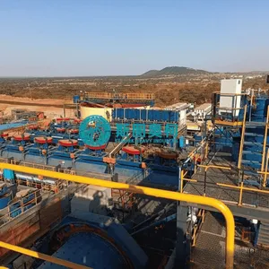
Flotation Cell Plant Design for Mineral Processing


Product Spotlights
Related Products
-
 Flotation Cell Circuit for Ore BeneficiationNegotiableMOQ: 1 Set
 -
2flotation Cell With Ball Mill Grinding SystemNegotiableMOQ: 1 Set
-
Flotation Cell With Crusher Grinding CircuitNegotiableMOQ: 1 Set
-
Flotation Cell for Flotation Plant LayoutNegotiableMOQ: 1 Set
-
Flotation Cell EPC Mining Project SupplierNegotiableMOQ: 1 Set
1.Product Introduction Flotation cell plant design for mineral processing
The flotation cell plant design for mineral processing is a comprehensive, system-wide engineering blueprint that choreographs the layout, capacity, and hydrodynamic flow of multiple flotation stages. Rather than focusing on a single machine, this plant design optimizes the spatial arrangement, piping networks, gravity drops, and equipment sizing of rougher, scavenger, and cleaner banks to ensure continuous, high-efficiency separation of target minerals from complex run-of-mine ores.
2.Application Flotation cell plant design for mineral processing
A well-engineered plant design must adapt to varying ore characteristics, kinetics, and production goals. The design framework is suitable for the following typical mineral processing applications: Complex Polymetallic Circuits: Such as copper-lead-zinc or copper-gold ores that require sequential or differential flotation stages to separate multiple valuable minerals into individual, high-purity concentrates. Large-Scale Industrial Concentration: Including high-tonnage porphyry copper operations or iron ore reverse-flotation plants where processing tens of thousands of tons per day demands flawless slurry distribution and minimal hydraulic bottlenecks. Industrial Scale Non-Metallic Processing: For minerals like potash, phosphate, fluorite, and coal, where the design must handle high solids concentration and highly abrasive pulp profiles without excessive equipment wear.
3.Working Principle Flotation cell plant design for mineral processing
The fundamental principle of flotation plant design is to translate laboratory and pilot kinetic data into a continuous, gravity-optimized or pump-driven physical layout. Kinetic Modeling and Scale-Up: Laboratory flotation test data is calculated using scale-up factors to determine the total volumetric capacity and the precise number of cells required in series to prevent short-circuiting of the slurry. Hydraulic and Elevation Design: The plant is typically designed in a stepped or terraced layout, allowing slurry to flow by gravity from the roughers down to the scavengers. This minimizes the reliance on internal slurry pumps, reduces energy consumption, and limits particle degradation. Circuit Configuration Control: The layout incorporates flexible piping, launders, and splitting boxes that allow operators to route intermediate streams, such as cleaner tailings, back to the head of the rougher circuit or to a regrind mill for further liberation.
4.Advantages Flotation cell plant design for mineral processing
Optimized Metallurgical Recovery: By precisely matching tank volumes and cell configurations to the ore's specific flotation kinetics, the plant design eliminates dead zones and short-circuiting, pushing mineral recovery to its theoretical maximum. Reduced Operational Expenditure: Strategic layout choices, such as maximizing gravity-driven slurry flow and consolidating reagent distribution points, significantly lower power consumption and simplify daily maintenance routines. Future-Proof Scalability: Advanced plant designs incorporate modular footprints, flexible launder paths, and built-in structural space, allowing mining companies to expand production capacity or adapt to changing ore grades with minimal structural modification.
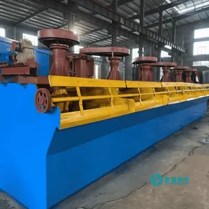
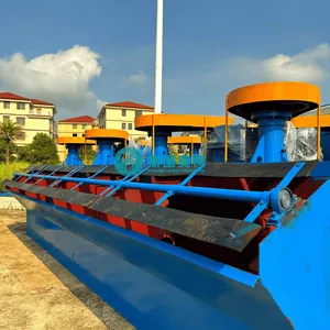
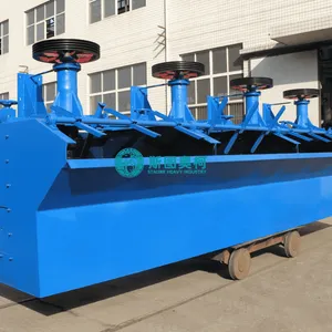
5.Technical Specifications
Category |
Model |
Effective Volume |
Capacity |
Impeller |
Impeller RPM Motor Power |
(kW)-Agitating |
Motor Power |
Single Weight (t) |
XJK type |
XJK-0.35 |
0.35 |
0.18-0.4 |
300 |
480 |
1.5 |
0.75 |
0.6 |
XJK-0.62 |
0.3-0.9 |
350 |
400 |
3 |
1.1 |
0.9 |
||
XJK-1.1 |
0.6-1.6 |
500 |
330 |
5.5 |
1.1 |
1.3 |
||
XJK-2.8 |
1.5-3.5 |
600 |
280 |
11 |
1.5 |
2.5 |
||
XJK-5.8 |
5.8 |
5-7 |
750 |
240 |
15 |
1.5 |
3.6 |
|
SF type Flotation |
SF-0.37 |
0.37 |
0.2-0.4 |
300 |
352-442 |
1.5 |
0.55 |
0.5 |
SF-0.65 |
0.65 |
0.3-1.0 |
350 |
336 |
3 |
1.1 |
1 |
|
SF-1.2 |
1.2 |
0.6-1.6 |
450 |
298 |
5.5 |
1.1 |
1.5 |
|
SF-2.8 |
2.8 |
1.5-3.5 |
550 |
268 |
11 |
1.5 |
2.3 |
|
SF-4 |
4 |
2-4 |
650 |
237 |
15 |
2.2 |
2.8 |
|
SF-8 |
8 |
4-8 |
760 |
191 |
30 |
2.2 |
4.3 |
|
SF-10 |
10 |
5-10 |
760 |
191 |
30 |
3 |
4.6 |
|
SF-16 |
16 |
6-16 |
850 |
180 |
45 |
3 |
7.8 |
|
SF-20 |
20 |
8-20 |
730 |
186 |
55 |
3 |
9.8 |
|
| JJF type Flotation machine | JJF-2 |
2 |
1-3 |
370 |
400 |
11 |
1.1 |
1.9 |
JJF-4 |
4 |
2-4 |
410 |
305 |
15 |
1.5 |
2.3 |
|
JJF-8 |
8 |
4-8 |
540 |
233 |
22 |
2.2 |
4.5 |
|
JJF-10 |
10 |
5-10 |
540 |
233 |
22 |
2.2 |
4.9 |
|
JJF-16 |
16 |
5-16 |
700 |
180 |
37 |
2.2 |
8.2 |
|
JJF-20 |
20 |
5-20 |
730 |
180 |
37 |
2.2 |
10.5 |

Send Inquiry to This Supplier


You May Also Like
-
Flotation Cell for Gravity Flotation PlantNegotiableMOQ: 1 Set
-
Flotation Cell for Gold Ore Concentration PlantNegotiableMOQ: 1 Set
-
Flotation Cell for Copper Ore Processing PlantNegotiableMOQ: 1 Set
-
Flotation Cell for Zinc Lead Flotation PlantNegotiableMOQ: 1 Set
-
36、flotation Cell for Refractory Gold OreNegotiableMOQ: 1 Set
-
Flotation Cell for Complex Ore BeneficiationNegotiableMOQ: 1 Set
-
Flotation Cell for Low Grade Ore UpgradeNegotiableMOQ: 1 Set
-
Flotation Cell for Mining Plant OptimizationNegotiableMOQ: 1 Set
-
Flotation Cell for Metallurgical PlantNegotiableMOQ: 1 Set
-
Flotation Cell for Mineral Processing EngineeringNegotiableMOQ: 1 Set


