

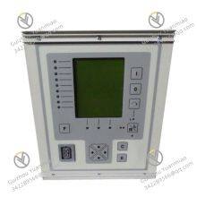
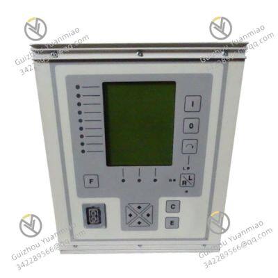
ABB REF541KM115AAA Feeder Termination
Related Products
-
 ABB RET670 1MRK002816-AC Digital Transformer Protection Intelligent Electronic DeviceNegotiableMOQ: 1 Piece
 -
ABB 07DC91C Digital Input ModuleNegotiableMOQ: 1 Piece
-
ABB DSQC602 Analog Output ModuleNegotiableMOQ: 1 Piece
-
ABB 3BHB019265R0410 Analogue Input/Output (I/O) ModuleNegotiableMOQ: 1 Piece
-
ABB R474A11XE HAFAABAAABE1BCA1XENegotiableMOQ: 1 Piece
ABB REF541KM115AAA is a feeder terminal (protective relay) designed specifically for medium‑voltage power grids. It serves as an all‑operating‑condition protection and intelligent monitoring hub for medium‑voltage feeder circuits. It is widely compatible with single‑bus, double‑bus, and dual systems, and supports various medium‑voltage grid earthing systems (6 kV–35 kV), including isolated neutral, Petersen coil earthed, and resistance‑earthed networks. It also provides protection and control for medium three‑phase asynchronous motors and shunt capacitor banks for reactive power compensation.
The device uses a 32‑bit high‑performance microprocessor and multi‑channel data acquisition system, complying with international and domestic protection standards such as IEC 61850 and GB/T 14285. With flexible programmability, rich communication capabilities, and high reliability, it is a key component in substation automation systems, widely used in power distribution and industrial distribution. It delivers accurate protection, intelligent control, and efficient operation and maintenance support for medium‑voltage feeders.
I. Functions and Advantages
1. Core Functions
Comprehensive Grid ProtectionIntegrates complete protection modules covering all medium‑voltage feeder fault conditions: non‑directional and directional overcurrent protection, earth‑fault protection (zero‑sequence current protection, low‑current earth‑fault selectivity), residual voltage protection, over/undervoltage protection, and thermal overload protection.It also supports circuit‑breaker failure protection (CBFP), auto‑reclosing, instantaneous overcurrent, time‑delayed instantaneous, definite‑time, and inverse‑time overcurrent protection.Fast fault response: short‑circuit protection ≤ 20 ms; overload protection ≤ 50 ms; earth‑fault protection ≤ 30 ms.Quickly isolates faults to avoid outages in healthy sections and ensure grid stability, adapting to various earthing systems.
Precise Measurement and Status MonitoringAcquires real‑time measurements via conventional instrument transformers or current/voltage sensors: phase currents, phase‑to‑phase voltages, phase‑to‑neutral voltages, residual current and voltage, frequency, power factor, active/reactive power, and energy.High accuracy: current/voltage ±0.2% FS; power/energy ±0.5% FS.Provides circuit‑breaker status supervision, trip‑circuit supervision, and internal self‑monitoring.Supports up to 200 fault records (10 s per record, 1 kHz sampling rate), providing reliable data for operation and fault analysis.
Flexible Control and PLC ProgrammabilitySupports local and remote control of switching devices, with status indication and bay‑ and station‑level interlocking.Built‑in comprehensive PLC functions integrate multiple automation and sequential logic control functions required for substation automation.Using the LON communication protocol reduces hard‑wiring between feeder terminals, fulfilling customized control requirements without extra control equipment and simplifying system architecture.
Multi‑Protocol CommunicationEquipped with dual communication interfaces: one for local communication with a PC, the other for remote communication via the substation communication system.Supports mainstream protocols: SPA bus, LON bus, IEC 60870‑5‑103, IEC 61850 (with SPA‑ZC 400), PROFIBUS DPV1 (with SPA‑ZC 302), DNP 3.0, and Modbus.Standard interfaces: EtherNet/IP, RS485 (Modbus‑RTU); optional: IEC 61850 MMS/GOOSE.Seamlessly integrates into Distribution Management Systems (DMS) or integrated substation automation systems, enabling remote setting adjustment, status monitoring, fault recording upload, and remote switching control.
Expansion and AdaptabilitySupports RTD / analog module expansion for temperature measurement, additional current/voltage measurement, and mA outputs.Provides 15 digital inputs and 12 output relays (some versions: 16 DI, 8 relay outputs, passive contacts AC 250 V / 5 A), allowing flexible connection to sensors and actuators.Supports fixed HMI (large graphical display, Chinese LCD) or external display modules for intuitive local operation and status viewing.
2. Key Advantages
High Reliability and StabilityIndustrial‑grade design with strong EMC performance complying with IEC 61000‑4 series, resisting lightning strikes and grid disturbances.Power supply includes surge protection and EMC filtering; input circuits use optical isolation (isolation voltage ≥ 2500 V AC).Ingress protection: IP54 (unit), dust‑ and splash‑proof, suitable for distribution rooms and switchgear.High‑quality components with MTBF > 100,000 hours.Full self‑monitoring detects internal faults early, ensuring stable long‑term operation and reducing maintenance costs.
High Flexibility and VersatilityCompatible with various switchgear for 6 kV–35 kV medium‑voltage grids and distribution systems, and suitable for motor and capacitor bank protection.Modular software design: protection logic and settings can be flexibly configured via ABB software (e.g., PCM600) without hardware changes, achieving high universality.
Easy Operation and MaintenanceIntuitive HMI and keypad for fast parameter setting, fault query, and status review.Displays fault code, cause, and waveform in real time for quick troubleshooting.Supports online parameter modification, firmware upgrade, and setting backup/restore.Modular design simplifies expansion and replacement, minimizing downtime.
Seamless System IntegrationAs a core part of ABB substation automation solutions, it integrates smoothly with ABB distribution equipment and supports multiple protocols for third‑party systems.Enables substation‑level automation and remote supervision, fulfilling “four‑remote” functions (telemetry, remote signaling, remote control, remote adjustment) for smart distribution networks and supporting digital transformation in power systems.
II. Technical Specifications
1. Core Performance and Protection
| Parameter | Value |
|---|---|
| Model | REF541KM115AAA |
| Type | Medium‑voltage feeder terminal, protective relay (REF 541 series) |
| Rated voltage class | Medium voltage: 6 kV–35 kV (adaptable via voltage transformers) |
| Rated current | 5 A / 1 A (input via CT, configurable by software) |
| Rated voltage | 100 V (line); 57.7 V (phase, standard PT secondary) |
| Protection response time | Short‑circuit ≤ 20 ms; Overload ≤ 50 ms; Earth‑fault ≤ 30 ms |
| Fault recording | 200 fault logs, 10 s each, 1 kHz sampling |
| PLC function | Built‑in programmable logic for automation and sequential control |
2. Communication and I/O
| Parameter | Value |
|---|---|
| Communication interfaces | Dual ports; standard: EtherNet/IP, RS485 (Modbus‑RTU); optional: IEC 61850 MMS/GOOSE |
| Supported protocols | SPA, LON, IEC 60870‑5‑103, IEC 61850, PROFIBUS DPV1, DNP 3.0, Modbus |
| Analog inputs | 6 current, 4 voltage |
| Digital inputs | 15 (16 in some versions) |
| Relay outputs | 12 (8 in some versions); passive contacts, AC 250 V / 5 A |
| Expansion | Supports RTD / analog modules for temperature, AI, AO |
3. Electrical and Environmental
| Parameter | Value |
|---|---|
| Supply voltage | DC 220 V / 110 V or AC 220 V; power consumption ≤ 25 W |
| Operating temperature | -25 ℃ ~ +70 ℃ |
| Storage temperature | -40 ℃ ~ +85 ℃ |
| Relative humidity | 5%–95%, non‑condensing |
| Ingress protection | IP54 (unit) |
| Mounting | Panel mount, flush mounting in switchgear |
| Altitude | ≤ 2000 m (derate above) |
| EMC | Complies with IEC 61000‑4 series; surge, ESD, and radiated immunity |
III. Application Areas
Power DistributionFeeder protection and monitoring in medium‑voltage substations, urban, rural, and industrial park distribution networks.Fast fault isolation and service restoration for improved power supply reliability.Supports “four‑remote” functions in substation automation systems.
Industrial DistributionMedium‑voltage distribution systems in factories, mines, metallurgy, and chemicals.Protection and control for workshop feeders, motors, and capacitor banks.Adapts to harsh industrial EMI environments and continuous production.
Other FieldsRail transit, new energy power station (PV, wind) distribution networks, large commercial complex distribution systems.Provides reliable protection and intelligent monitoring for medium‑voltage feeders.
IV. Installation and Commissioning Guide
1. Pre‑Installation Preparation
Compatibility CheckConfirm REF541KM115AAA matches the on‑site voltage class (6 kV–35 kV), CT rating (5 A/1 A), and earthing system.Verify auxiliary supply (DC 220 V/110 V or AC 220 V) and communication protocol compatibility with the substation automation system.
Environment CheckAmbient temperature: -25 ℃ ~ +70 ℃; humidity: 5%–95% non‑condensing.Install away from inverters, high‑power motors, and strong interference sources.Location must allow convenient operation and maintenance; cabinet protection grade preserves IP54 performance.
Tools and MaterialsPrepare anti‑static wristband, screwdrivers, multimeter, oscilloscope, communication cables (EtherNet/IP, RS485), terminals, insulation test tools.Verify accessories against packing list.Installation and commissioning are recommended to be performed by ABB‑certified specialists or professional maintenance personnel.
2. Hardware Installation
Power‑Off ProcedureDisconnect main power before installation; wait at least 10 minutes for internal capacitors to discharge.Wear anti‑static wristband to prevent electric shock or ESD damage.
Unit MountingFlush‑mount the unit in the designated position in the switchgear as per layout and instructions.Ensure firm, level installation with reliable contact; leave sufficient heat dissipation space.
Wiring Rules
Power supply: Connect rated auxiliary power with correct polarity; use fuse protection. Verify auxiliary power stability.
Signals: Connect CT and VT signals to analog inputs with correct phase sequence and polarity. Secure wiring to avoid measurement errors or maloperation. Connect DI and DO according to terminal definition.
Communication: Connect cables to PC and automation system; shield grounded reliably to reduce EMI. Fix cable routes and perform internal serial communication analysis.
Grounding: Connect unit earth terminal to switchgear protective earth (earth resistance ≤ 4 Ω). Verify cabinet grounding, insulation, and internal wiring.
3. Software Configuration
Device ConnectionOpen ABB configuration software (e.g., PCM600), connect to REF541KM115AAA, establish communication, read default parameters.
Parameter Setting
Basic: Set voltage class, CT/VT ratios, and supply parameters.
Protection: Set overcurrent, earth‑fault, over/undervoltage thresholds, response times, and autoreclose parameters according to load and system requirements.
Communication: Configure protocol, address, baud rate for compatibility with host systems (SAS, DMS).
PLC logic: Program sequential and interlocking functions as required.
Download and BackupDownload parameters to the unit and restart to activate.Save configuration files and setting groups for backup, restore, and batch configuration.
4. Commissioning and Verification
Power‑On TestPower LED (PWR) steady, Run LED (RUN) flashing, no fault alarms.Check parameters and self‑monitoring via HMI.
Communication TestSend commands from host system; read measurements and fault records to verify stable and accurate data exchange.Perform serial communication analysis for DCS and SCADA.
Function Test
Protection: Simulate short‑circuit, overload, earth‑fault; verify correct tripping, alarming, and fault recording.
Control: Test local/remote control, switching operation, and PLC logic. Verify motor and capacitor bank protection if applicable.
Measurement: Compare readings with standard instruments to confirm accuracy ±0.2% FS.
On‑Site Joint CommissioningConnect to actual feeder circuit and run full operation.Confirm stable performance of protection, control, and communication.Perform system analysis and optimization.Document all steps, settings, and test results for future reference.
V. Common Problems
No power / unit fails to startCheck power wiring, voltage (DC 220 V/110 V or AC 220 V), fuse, and auxiliary supply.Verify power interface and connections.
Communication abnormalityCheck cable connections, shield grounding, and parameters (address, baud rate, protocol).Eliminate bus interference and inspect communication ports.Review cable routing and re‑perform serial communication analysis.
Abnormal measurement dataCheck CT/VT wiring, polarity, and ratio settings.Troubleshoot sensors and analog input channels.Calibrate measurement accuracy to ±0.2% FS.
Protection maloperation / failure to operateVerify setting values, load characteristics, and grid type.Check fault simulation conditions and input interference.Inspect relay output circuits for correct fault tripping.
Fault recording unavailableCheck fault log settings and storage space.Verify communication for remote viewing.Restart unit to restore function.
PLC logic abnormalCheck program correctness and conflicts.Verify DI/DO wiring and field devices.Reload program and re‑test logic.

Send Inquiry to This Supplier


You May Also Like
-
ABB CRBX01 2VAA008424R1 Remote Bus ExtenderNegotiableMOQ: 1 Piece
-
ABB FET3251C0P184C0H2 Power Control Board / Process Transmitter Companion UnitNegotiableMOQ: 1 Piece
-
ABB UNITROL1005-0011 ECO 3BHE043576R0011 Industrial‑grade Control ModuleNegotiableMOQ: 1 Piece
-
ABB SAFT183VMC Control ModuleNegotiableMOQ: 1 Piece
-
ABB REJ601BD446NN1XG Relion® 605 Series Feeder Protection RelayNegotiableMOQ: 1 Piece
-
ABB XVC768AE102 3BHB007211R0102 16-Channel AC Digital Input ModuleNegotiableMOQ: 1 Piece
-
ABB PM858-C 3BSE093350R1 AC 800M Series CPU ModulesNegotiableMOQ: 1 Piece
-
ABB CB801 3BSE042245R1 PROFIBUS DP Communication Interface ModuleNegotiableMOQ: 1 Piece
-
ABB SCYC51204 63912476C Transient Absorption ModuleNegotiableMOQ: 1 Piece
-
ABB CP450-T-ETH 10.4-inch Colour Touchscreen Human-machine InterfaceNegotiableMOQ: 1 Piece


