








 Contact Platform Support
 Help Center
WOODWARD 8273-1014 Steam Turbine Control



Related Products
-
 WOODWARD 8237-2046 2301E-HT Hydro Turbine ControlNegotiableMOQ: 1 Piece
 -
WOODWARD 8200-1400 Low Voltage Direct Current (LVDC)NegotiableMOQ: 1 Piece
-
WOODWARD 8200-1403 Francis/Kaplan TurbinesNegotiableMOQ: 1 Piece
-
WOODWARD 8200-1401 505HT for Pelton TurbinesNegotiableMOQ: 1 Piece
-
WOODWARD 8269-1073 17" OCP TouchpanelNegotiableMOQ: 1 Piece
I. Overview
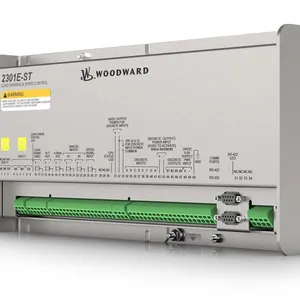
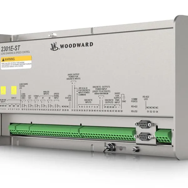
WOODWARD 8273-1014 is a steam turbine control module, whose core positioning is to provide core control and protection functions for small steam turbine packages. Equipped with the 2301E-ST application software, this product features high configurability, allowing flexible adjustment of parameters and functional logic according to the requirements of specific sites. Meanwhile, it supports the MODBUS communication protocol, enabling convenient integration with on-site PLC or plant DCS systems, thus providing full-process hardware and software support for the stable operation, precise regulation and safety protection of small steam turbines.
With high reliability, strong environmental adaptability and excellent backward compatibility (maintaining consistency in form, adaptability and functions with classic models of the same series), this product is widely used in core scenarios such as power generation systems driven by small steam turbines, industrial steam power systems, pump stations and compressors. It meets various supporting needs including system construction, equipment upgrading and transformation, as well as operation and maintenance replacement, ensuring the efficient and safe operation of steam turbines under different working conditions.
II. Product Features
Integrated Core Control and Protection: It deeply integrates the core control functions and safety protection functions required for small steam turbine packages, enabling precise speed control, load regulation and safe shutdown protection under abnormal working conditions of steam turbines, thus comprehensively ensuring the safe operation of equipment.
Highly Flexible Configurability: Equipped with the configurable 2301E-ST application software, it supports flexible configuration of control logic, parameter thresholds and input/output interface functions according to the process requirements and operating conditions of specific sites, adapting to diverse application scenarios.
Redundant Design for Enhanced Reliability: It supports two redundant microprocessor speed signal inputs, effectively avoiding control failure caused by single signal source faults, significantly improving the reliability and stability of system operation. Key states are equipped with multiple monitoring mechanisms to reduce the risk of faults.
Convenient Communication and Interaction: It is provided with independent RS-232 and RS-422 serial communication interfaces (both with 9-pin connectors), supporting the MODBUS communication protocol, which can quickly realize docking with on-site PLC and plant DCS systems, facilitating remote monitoring, parameter configuration and data interaction. LED indicators are equipped for power supply and RS-422 communication status to visually feedback the operation status.
Comprehensive Fault Tracing Capability: It has a fault data recording function, which can collect operation data every 10 milliseconds for 16 consecutive seconds, focusing on capturing data of key fault nodes such as shutdown, peak speed and load abnormality, providing accurate basis for fault diagnosis and cause tracing.
Wide Drive Compatibility and Backward Compatibility: It supports driving WOODWARD L-series, F-series, P-series and PISC drives, with low-current pressure wave M output. It maintains consistency in form, adaptability and functions with classic models of the same series (such as 2231D-ST), achieving seamless backward compatibility and reducing the difficulty and cost of system upgrading and transformation.
III. Technical Parameters
1. Core Basic Parameters
Product Model: WOODWARD 8273-1014
Product Type: Small Steam Turbine Control and Protection Module
Manufacturer: WOODWARD
Core Software: 2301E-ST Application Software (Configurable)
Core Functions: Steam turbine speed control, load regulation, safety protection, fault data recording, communication interaction with upper-level systems
Operation Modes: Supports 4 core operation modes—Speed Control Mode, Isochronous Load Sharing Mode, Droop Base Load Mode, Isochronous Base Load Mode
Adapted Systems: Small steam turbine packages, on-site PLC systems, plant DCS systems
Application Fields: Power generation systems driven by small steam turbines, industrial steam power systems, pump stations, compressors, etc.
2. Electrical Performance Parameters
Supply Voltage: 24V DC (DC Power Supply)
Speed Signal Input: 2 channels of redundant microprocessor speed signal inputs (redundant design for enhanced reliability)
Control Signal Output: Low-current pressure wave M output (adapted to L/F/P/PISC series drives)
Communication Interfaces: 1 channel of RS-232 serial port, 1 channel of RS-422 serial port (both equipped with 9-pin connectors)
Communication Protocol: Supports MODBUS communication protocol
I/O Configuration: The added terminal block can accommodate additional input/output interfaces, and the position of core terminals is compatible with the 2231D-ST model
Remote Control: Supports remote speed reference adjustment through configurable analog input (4-20mA)
3. Environmental and Physical Parameters
Operating Temperature: -20℃~+60℃ (wide-temperature design, adapted to complex industrial site environments)
Storage Temperature: -40℃~+85℃
Relative Humidity: 5%~95% RH (no condensation)
Protection Grade: IP20 (suitable for indoor control cabinet installation, preventing solid foreign matter intrusion)
Installation Method: DIN rail mounting (adapted to standard industrial rails)
IV. Working Principle
The core working principle of WOODWARD 8273-1014 is a closed-loop collaborative process of "signal acquisition - logical operation - control output - status feedback - fault recording". Through the coordinated operation of internal microprocessors, signal processing units, communication units and fault recording units, it realizes full-process precise control and safety protection of small steam turbines. The specific working process can be divided into five core stages:
Stage 1: Initialization and Configuration StageAfter the module is connected to a 24V DC power supply, it completes initialization and startup, automatically conducting internal circuit self-test, interface calibration and software loading. Through upper-level systems or local configuration tools, operation and maintenance personnel complete the configuration of key parameters such as operation modes (speed control/load sharing, etc.), control parameter thresholds, communication protocol parameters and I/O interface functions based on the 2301E-ST software, ensuring the precise adaptation of the module to steam turbines and PLC/DCS systems.
Stage 2: Signal Acquisition StageThe module collects the speed signal of the steam turbine in real time through 2 channels of redundant speed signal input channels. At the same time, it receives key operating parameters such as load signals and pressure signals fed back by on-site sensors, as well as remote control signals issued by upper-level systems (such as 4-20mA speed reference signals). During the acquisition process, the built-in filter circuit preprocesses the signals to remove clutter interference and improve data accuracy.
Stage 3: Logical Operation and Decision-making StageBased on the collected real-time data and preset control logic, the internal microprocessor completes operational decisions such as speed regulation and load distribution. According to the current operation mode, it dynamically adjusts the control strategy—for example, accurately adjusting the speed to the reference value in the speed control mode, and realizing synchronous load distribution of multiple devices in the isochronous load sharing mode, ensuring that the operation status of the steam turbine meets the process requirements.
Stage 4: Control Output and Execution StageThe module sends the control commands generated by operation to WOODWARD L/F/P/PISC series drives through the low-current pressure wave M output channel, driving the action of steam turbine regulating mechanisms (such as throttle valves and steam valves) to achieve precise regulation of speed or load. Meanwhile, it monitors the response status of the regulating mechanism in real time to ensure the effective execution of control commands.
Stage 5: Status Feedback and Fault Handling StageThe module uploads the steam turbine operating parameters and its own working status (such as power supply status and communication status) to the upper-level PLC/DCS system in real time through the MODBUS protocol, providing data support for remote monitoring. The fault recording unit collects operation data every 10 milliseconds. When faults such as shutdown, peak speed abnormality and load over-limit are detected, it immediately triggers safety protection mechanisms (such as emergency shutdown) and saves the fault data within 16 seconds to facilitate subsequent tracing and analysis.
V. Common Fault Troubleshooting
1. Abnormal Speed Signal / Deviation in Control Accuracy
Phenomenon: The speed data displayed by the module deviates significantly from the actual speed of the steam turbine; the speed fluctuates frequently and cannot be stabilized at the reference value; the redundant speed signal input alarms; speed control fails.
Causes: Aging, damage or improper installation position of the speed sensor; loose, poor contact, damaged or short-circuited speed signal lines; signal transmission affected by electromagnetic interference; incorrect configuration of module speed parameters (such as reference value, gain, filter parameters); fault of redundant signal input channels.
Solutions:
Check whether the appearance of the speed sensor is damaged, use professional tools to detect the output signal of the sensor and confirm whether it is within the normal range; if the sensor is faulty, replace it with a genuine sensor of the same model; adjust the installation position of the sensor to ensure accurate signal acquisition.
Disconnect the power supply, check the wiring of the speed signal lines, tighten loose connectors, repair or replace damaged and short-circuited lines.
Replace the original lines with shielded cables, keep the signal lines away from strong electromagnetic interference sources such as frequency converters and high-power motors, and reliably ground one end of the shielded cable (grounding resistance ≤4Ω) to reduce the impact of interference.
Enter the module configuration interface, check the speed reference value, gain, filter and other parameters, adjust them to a reasonable range and conduct retesting.
Test the redundant speed signal input channels to locate the faulty channel. If the internal channel of the module is faulty, contact WOODWARD official after-sales service for maintenance.
2. Communication Link Interruption / Abnormal Data Interaction
Phenomenon: The module cannot establish communication with the PLC/DCS system; operation data transmission is frequently interrupted or packet loss occurs; the upper-level system cannot issue control commands or parameter configuration fails; the RS-422 communication status indicator is abnormal.
Causes: Loose, poor contact or damaged communication lines (RS-232/RS-422); incorrect configuration of communication parameters (such as mismatched protocol type, address, baud rate); communication interface failure (damaged 9-pin connector); fault of the built-in communication unit of the module; fault of the communication module of the upper-level system.
Solutions:
Disconnect the power supply, check the connection status of the communication lines, re-plug and tighten the connectors, replace damaged and aging lines.
Check the communication parameters (protocol, address, baud rate, etc.) between the module and the upper-level system to ensure they are completely consistent, reconfigure and restart the communication link.
Check whether the 9-pin communication connector is damaged or oxidized, clean the impurities in the interface or replace the connector.
Switch the communication interface (e.g., switch from RS-422 to RS-232) for testing to locate the faulty interface.
If the above measures are ineffective, the built-in communication unit of the module or the communication module of the upper-level system may be faulty. They need to be tested separately and the corresponding manufacturer's after-sales service should be contacted for maintenance.
3. Abnormal Power Supply / Failure to Start the Module
Phenomenon: After being connected to a 24V DC power supply, the module cannot start and the power indicator has no response; the module frequently shuts down due to power supply problems during operation; the power status indicator flashes abnormally.
Causes: The supply voltage does not meet the 24V DC standard (too high or too low); loose, poor contact or reversed positive and negative poles of the power interface; excessive voltage fluctuation caused by the failure of the external power module; short circuit or component aging of the internal power supply circuit of the module; the fuse circuit breaker in the cabinet is not closed or damaged.
Solutions:
Use a multimeter to detect the voltage of the power supply to ensure it is stably at the 24V DC standard. If the voltage fluctuates excessively, replace the regulated power supply module.
Re-plug the power interface, tighten the connector, check the positive and negative wiring of the power supply and correct the wrong wiring.
Check the status of the fuse circuit breaker in the cabinet to ensure it is closed and undamaged; replace it with a fuse of the same specification in case of damage.
Disconnect the power supply, wait for 5 minutes, then reconnect the power supply and try to start the module.
If the module still cannot start or the power supply is abnormal, the internal power supply circuit of the module may be faulty. Contact WOODWARD official after-sales service for maintenance.
4. Frequent Triggering of Fault Recording / Malfunction of Protection Mechanism
Phenomenon: The module frequently triggers the fault recording function; the safety protection mechanism (such as emergency shutdown) is triggered under no obvious abnormal working conditions; alarms for peak speed and load abnormality are frequent.
Causes: The protection parameter threshold is set too low (such as unreasonable setting of peak speed and load upper limit); data misjudgment caused by sensor signal interference; incorrect configuration of control logic; abnormal signal processing caused by internal faults of the module.
Solutions:
Retrieve the fault recording data of the module, analyze the key parameters triggering the fault, adjust the protection parameter threshold to a reasonable range in combination with the actual on-site working conditions.
Check the anti-interference measures of the sensor signal lines, enhance shielding protection, keep away from strong electromagnetic interference sources to reduce signal interference.
Recheck the module control logic configuration and correct wrong logic settings.
If the fault is still frequently triggered, the internal signal processing unit of the module may be faulty. Contact WOODWARD official after-sales service for testing.

Send Inquiry to This Supplier


You May Also Like
-
WOODWARD 8928-5311 RemoteViewNegotiableMOQ: 1 Piece
-
WOODWARD 8200-1500 ControllerNegotiableMOQ: 1 Piece
-
WOODWARD 8200-1502 Original Instructions ManualNegotiableMOQ: 1 Piece
-
WOODWARD 8200-1505 Manuals and User GuidesNegotiableMOQ: 1 Piece
-
WOODWARD 8200-1310 Logic Controller ModuleNegotiableMOQ: 1 Piece
-
WOODWARD 8200-1312 Digital Governor Turbine ControlNegotiableMOQ: 1 Piece
-
WOODWARD 8200-1330 Digital ControllerNegotiableMOQ: 1 Piece
-
WOODWARD 5541-705 Discrete Input 20 Through Relay 8 InterlockNegotiableMOQ: 1 Piece
-
WOODWARD 8200-1203 LinkNet-HT Analog 4-20 mA ModuleNegotiableMOQ: 1 Piece
-
WOODWARD 8200-1200 LinkNet-HT RTD ModuleNegotiableMOQ: 1 Piece


