








 Contact Platform Support
 Help Center
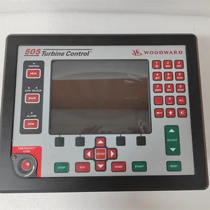
WOODWARD 5541-705 Discrete Input 20 Through Relay 8 Interlock




Related Products
-
 WOODWARD 8200-1203 LinkNet-HT Analog 4-20 mA ModuleNegotiableMOQ: 1 Piece
 -
WOODWARD 8200-1200 LinkNet-HT RTD ModuleNegotiableMOQ: 1 Piece
-
WOODWARD 8262-1142 5009XT With 2 220 VAC PSNegotiableMOQ: 1 Piece
-
WOODWARD 8262-1141 5009XT With 2 120 V AC/DC PSNegotiableMOQ: 1 Piece
-
WOODWARD 8262-1143 5009XT With 2 24 VDC PSNegotiableMOQ: 1 Piece
I. Overview
The WOODWARD 5541-705 is an electronic governor, positioned as a Precision Engine Speed Control and Operation Safety Protection Terminal. It is part of Woodward’s 8200 series of general-purpose speed control products. Leveraging advanced digital control technology, this governor features fast response and strong anti-interference capability. It can collect real-time engine speed signals and external control commands, and through its internal precision PID control algorithm and high-reliability power drive circuit, it outputs accurate execution signals to drive fuel injection systems or gas control valves, achieving closed-loop stable control of engine speed.
Compatible with engines of various cylinder diameters and fuel types, it is widely used in applications such as diesel/gas generator sets, marine power systems, industrial compressors, heavy construction machinery, and oilfield power equipment. It provides core control support for the efficient, stable, and safe operation of engines under all working conditions, ensuring the consistency and reliability of power output while reducing energy consumption and operation and maintenance risks.
Adopting an industrial-grade enhanced protection design, the device not only ensures core speed regulation performance but also has excellent adaptability to harsh environments, withstanding common industrial interferences such as vibration, high temperature, humidity changes, and dust erosion. Based on Woodward’s mature power control technology system, the 5541-705 governor supports flexible interaction of multiple analog and discrete signals, enabling seamless integration with mainstream PLC and DCS control systems for remote monitoring and centralized control. It also incorporates built-in functions including speed deviation alarm, overload protection, and full-dimensional fault self-diagnosis. It can quickly respond to engine operation abnormalities and trigger preset protection actions, effectively reducing maintenance difficulty and downtime losses. It is suitable for new power system construction, retrofitting of old governors, and power control scenarios with high reliability requirements.
II. Product Features
High-precision Closed-loop Speed Control: Equipped with an upgraded digital PID control algorithm integrated with an adaptive load compensation strategy, the speed regulation accuracy can reach ±0.2% of the rated speed. It can accurately respond to sudden load fluctuations of the engine, quickly suppress speed deviations, and ensure stable engine operation under all working conditions including idle speed, rated speed, and transient conditions. It supports adjustable speed soft start and soft stop functions with customizable start/stop ramps, significantly reducing the wear of engine mechanical components caused by start-up impact and extending equipment service life.
Wide Adaptability and Multi-fuel Compatibility: It can flexibly adapt to diesel engines and gas engines with a cylinder diameter range of 50mm~320mm (compatible with multiple fuel types such as natural gas, liquefied petroleum gas, and biogas). It supports the speed regulation needs of engines with different power levels. Parameter matching can be completed through dedicated configuration software without modifying the hardware structure, offering extremely strong adaptability to meet the control requirements of power equipment in various scenarios.
Rich Signal Interaction and Expansion Capability: It is equipped with 3 analog input channels (for connecting speed sensor signals, load feedback signals, throttle position signals, etc.), 2 analog output channels (for driving actuators or feeding back operating parameters), and 6 discrete input/4 discrete output channels (for controlling start/stop, triggering alarms, linking protection devices, etc.). It supports standard industrial signals such as 4-20mA and 0-10V, enabling seamless integration with mainstream PLC and DCS control systems (e.g., Siemens, Schneider) to easily achieve remote speed regulation, status monitoring, and interlock control.
Full-dimensional Fault Diagnosis and Multi-layer Protection: Built-in full-dimensional diagnostic functions cover speed sensor faults, actuator faults, power supply abnormalities, speed over-limit, etc., enabling real-time monitoring of equipment operating status. When detecting engine overspeed, underspeed, excessive speed fluctuation, or governor internal faults, it immediately triggers sound and light alarm signal output and executes preset protection actions (such as limiting maximum throttle opening, cutting off fuel/gas supply, triggering emergency shutdown), forming multi-layer safety protection to maximize the safety of engines and personnel.
Strong Environmental Adaptability and Stable Operation Performance: Utilizing industrial-grade high-stability electronic components and a sealed protective structure, it achieves an IP54 protection rating and can operate stably in a wide temperature range of -40℃~+85℃. It boasts excellent anti-vibration performance (vibration frequency 10-2000Hz, acceleration 20g) and anti-electromagnetic interference capability, complying with EN 61000-6-2 (immunity) and EN 61000-6-4 (emission) standards. It can withstand strong electromagnetic environments and mechanical vibration impacts in industrial sites, ensuring the stability and reliability of speed regulation control.
Convenient Parameter Configuration and Maintenance Design: It supports parameter setting via dedicated configuration software (compatible with Windows systems) or local knobs, allowing quick completion of operations such as speed setting, PID parameter adjustment, protection threshold configuration, and signal type selection. Equipped with high-definition status indicator lights and a fault code display window, it enables maintenance personnel to intuitively judge the equipment operating status and fault type. It also supports fault log storage and export functions, simplifying debugging and maintenance processes and reducing operation and maintenance costs.
III. Technical Parameters
1. Core Basic Parameters
Product Model: WOODWARD 5541-705
Product Type: Electronic Governor (Applicable to diesel/gas engines)
Manufacturer: Woodward Company
Product Series: WOODWARD 8200 Series
Core Functions: Precision engine speed control, speed soft start/soft stop, adaptive load compensation, full-dimensional fault self-diagnosis, overload protection, remote control signal interaction
Applicable Engine Types: Diesel engines, gas engines (natural gas, liquefied petroleum gas, biogas, etc.)
Applicable Engine Cylinder Diameter: 50mm ~ 320mm
Control Method: Closed-loop digital PID control with adaptive load compensation
Communication and Signal Interaction: Supports analog and discrete signal interaction, compatible with PLC and DCS systems
Application Fields: Diesel/gas generator sets, marine power systems, industrial compressors, heavy construction machinery (excavators, loaders, cranes), oilfield power equipment, mining machinery, etc.
2. Electrical Performance Parameters
Supply Voltage: 12V DC / 24V DC dual-voltage adaptive (wide voltage range: 10V DC ~ 32V DC)
Static Current Consumption: ≤ 160mA (12V DC supply); ≤ 90mA (24V DC supply)
Output Driving Capacity: Maximum output current 6A (for driving fuel actuators/gas control valves)
Analog Input: 3 channels, supporting standard signals of 4-20mA / 0-10V, input impedance ≥10kΩ
Analog Output: 2 channels, 4-20mA / 0-10V optional, load capacity ≤500Ω
Discrete Input: 6 channels, passive contact or NPN/PNP level signal, response time ≤10ms
Discrete Output: 4 channels, relay output (rating: 2A/250V AC, 5A/30V DC)
Speed Signal Input: Supports magnetoelectric speed sensors (sine wave signal, amplitude ≥0.5V rms) or Hall-effect speed sensors (square wave signal)
Speed Regulation Range: 50rpm ~ 3000rpm (extendable to 50rpm ~ 6000rpm via parameter setting)
Speed Regulation Accuracy: ±0.2% of rated speed
Response Time: ≤ 40ms (at 10% speed deviation)
Soft Start/Soft Stop Ramp: Adjustable (0.5~10s)
3. Environmental and Physical Parameters
Operating Temperature: -40℃ ~ +85℃
Storage Temperature: -55℃ ~ +125℃
Relative Humidity: 0% ~ 95% RH (no condensation)
Protection Rating: IP54 (compliant with IEC 60529 standard)
Anti-vibration Performance: Frequency 10-2000Hz, acceleration 20g (compliant with MIL-STD-810 standard)
Electromagnetic Interference Resistance: Compliant with EN 61000-6-2 (immunity) and EN 61000-6-4 (emission) standards
Housing Material: Die-cast aluminum alloy with anodized surface treatment
Weight: Approximately 1.3kg (including mounting bracket)
Installation Method: Flange mounting / bracket mounting, with the mounting plane parallel to the engine crankshaft centerline
Installation Torque: Fixing bolt torque 4.5N·m ~ 6.0N·m
Wiring Method: Screw-type terminals for easy fastening and maintenance
IV. Working Principle
The core working principle of the WOODWARD 5541-705 governor is a closed-loop control process of Speed Signal Collection - Deviation Calculation - Precision Drive - Status Feedback - Fault Response. Through the coordinated operation of its internal signal collection unit, control calculation unit, power drive unit, and fault diagnosis unit, it achieves real-time precision control of engine speed and ensures safe operation. The specific working process can be divided into five core stages:
Stage 1: System Initialization and Parameter ConfigurationAfter the governor is powered on, it automatically completes the initialization process, performing internal circuit self-test, sensor interface connectivity detection, and actuator connection status verification. Maintenance personnel configure core parameters via dedicated configuration software or local knobs, including rated speed, idle speed, PID adjustment parameters (proportional gain, integral time, derivative time), overspeed/underspeed protection thresholds, soft start/soft stop ramp settings, and signal input/output type selection. This ensures the governor is accurately adapted to the target engine and control system to meet the control requirements of specific working conditions.
Stage 2: Real-time Speed Signal CollectionThe governor collects real-time engine crankshaft speed signals through matched speed sensors (magnetoelectric or Hall-effect type). The signal collection unit filters, amplifies, and shapes the speed signals, effectively eliminating signal noise caused by mechanical vibration and electromagnetic interference. It converts the collected analog or digital signals into standardized speed data and transmits it to the control calculation unit. Meanwhile, the collection unit synchronously receives auxiliary input signals such as external load feedback signals and throttle position feedback signals, providing comprehensive data support for precision speed regulation and load compensation.
Stage 3: Speed Deviation Calculation and Control Command GenerationThe control calculation unit compares the real-time collected actual speed data with the preset target speed (idle speed/rated speed) to accurately calculate the speed deviation value. Based on the preset digital PID control algorithm, combined with load change trends and adaptive compensation strategies, it processes the speed deviation value to generate precise control commands (e.g., drive signal parameters for adjusting fuel injection volume or gas supply volume), ensuring the control commands can quickly and smoothly eliminate speed deviations to achieve stable speed control.
Stage 4: Power Drive and Execution RegulationThe power drive unit converts the control commands generated by the control calculation unit into power signals that can directly drive actuators (fuel injection actuators, gas control valves). According to the parameters of the control commands, it precisely adjusts the action amplitude and speed of the actuators, realizing real-time dynamic adjustment of fuel or gas supply volume. This, in turn, changes the engine’s output power and speed, making the actual speed quickly approach and stabilize at the target speed.
Stage 5: Status Feedback and Fault ResponseThe fault diagnosis unit real-time monitors the speed signal collection status, actuator action feedback status, power supply voltage status, and its internal circuit working status, making comprehensive judgments based on preset protection thresholds. If engine overspeed, underspeed, excessive speed fluctuation, sensor faults, actuator jamming, or power supply abnormalities are detected, it immediately triggers a multi-layer protection mechanism: on the one hand, it sends an alarm signal to the control system or on-site sound and light alarm device through the discrete output interface; on the other hand, it executes preset protection actions (such as limiting maximum throttle opening, cutting off fuel/gas supply, triggering emergency shutdown). At the same time, the status indicator lights synchronously reflect the fault type, and fault codes are stored locally and can be exported via configuration software, facilitating maintenance personnel to quickly locate and resolve faults.
V. Common Fault Troubleshooting
1. Governor No Response, Engine Fails to Start
Phenomenon: The status indicator light does not illuminate after the governor is powered on; cannot connect to the governor via configuration software; the engine has no response after a start command is sent; the governor has no drive signal output to the actuator.
Causes: Abnormal supply voltage (missing, too low, or too high, outside the range of 10V DC ~ 32V DC); loose, poorly connected, or damaged power supply lines; oxidized, loose, or faulty governor power interface; damaged internal power module of the governor; invalid input of the start control signal (faulty discrete input interface or open/short circuit in the line).
Solutions: 1. Use a high-precision multimeter to measure the governor’s supply voltage to ensure it is within the standard range. If the voltage is abnormal, troubleshoot the power supply (battery, switching power supply) and power supply lines, repair damaged lines, and tighten loose connections. 2. Check if the governor’s power interface is oxidized or loose, clean impurities from the interface, reinsert the power plug, and replace the power interface terminal if necessary. 3. Test the start control signal (discrete input) by measuring the input interface level or contact on-off status with a multimeter to confirm valid signal input. If the signal is abnormal, troubleshoot the control signal line or front-end control equipment (PLC, start button). 4. If all the above inspections are normal, it is determined that the governor’s internal power module or core control circuit is damaged; contact Woodward’s official after-sales service for repair or replacement.
2. Excessive Engine Speed Fluctuation, Unstable Operation
Phenomenon: Engine speed fluctuation exceeds ±1% of the rated speed at idle or rated speed; slow speed recovery when the load changes; the governor’s status indicator light flashes frequently (no fault code displayed); the actuator operates frequently but the speed remains unstable.
Causes: Improper PID control parameter configuration (excessively high/low proportional gain, excessively long/short integral time, mismatched with load characteristics); loose, poorly spaced, or damaged speed sensor installation; electromagnetic interference on the speed signal line causing signal distortion; jammed, worn, or slow-responding actuator; clogged fuel/gas supply system or unstable pressure; unreasonable soft start/soft stop ramp settings.
Solutions: 1. Re-optimize the PID control parameters based on the engine’s load characteristics and working conditions. Gradually adjust the proportional gain and integral time via configuration software (it is recommended to first fix the integral time, adjust the proportional gain until there is no obvious fluctuation, then fine-tune the integral time to eliminate static deviation). Enable the adaptive load compensation function if necessary. 2. Check the speed sensor installation status to ensure the gap between the sensor and the signal gear meets requirements (usually 0.5mm ~ 1.5mm), and tighten the sensor fixing bolts. Use an oscilloscope to test the sensor output signal; replace the speed sensor if the signal amplitude is too small or the waveform is distorted. 3. Inspect the speed signal line, keep it away from strong electromagnetic interference sources such as frequency converters and high-voltage lines, use shielded cables with reliable grounding (ground resistance ≤4Ω), and repair damaged lines. 4. Check the actuator operation status, disassemble and clean impurities inside the actuator, test the actuator response speed, and replace the actuator if it is jammed or slow-responding. 5. Troubleshoot the fuel/gas supply system, clean filters and nozzles, test the supply pressure, and ensure stable fuel/gas supply. 6. Verify the soft start/soft stop ramp parameters and adjust them to a reasonable range based on engine characteristics.
3. Governor Alarms for Overspeed/Underspeed, Triggers Protective Shutdown
Phenomenon: The engine suddenly triggers an overspeed/underspeed alarm during operation, the governor outputs a protection signal, and the engine shuts down emergently; the controller displays an overspeed/underspeed fault code; the fault may recur after restarting.
Causes: Unreasonable overspeed/underspeed protection threshold settings (too low, mismatched with the engine’s rated speed); faulty speed sensor causing incorrect speed signal collection or distortion; excessive sudden load changes leading to delayed governor response; actuator faults (failure to adjust fuel/gas supply in a timely manner); interrupted or excessive fuel/gas supply; engine mechanical faults (e.g., jammed fuel injectors, valve faults, crankshaft abnormalities).
Solutions: 1. Verify the overspeed/underspeed protection thresholds via configuration software and reset them to reasonable values based on the engine’s rated speed (it is recommended to set the overspeed threshold to 115%-120% of the rated speed and the underspeed threshold to 80%-85% of the rated speed). 2. Check the speed sensor working status and test with a spare sensor to eliminate incorrect signal collection caused by sensor faults. 3. Analyze load change conditions; if sudden load changes occur, optimize the front-end load control strategy to avoid load shocks. Adjust the governor’s PID parameters to improve response speed and enable the adaptive load compensation function. 4. Inspect the actuator and fuel/gas supply system to ensure the actuator operates normally and the supply system is free of blockages or leaks; repair abnormal components. 5. If all the above inspections are normal, troubleshoot engine mechanical faults and conduct a comprehensive overhaul of the engine (e.g., inspect fuel injectors, valves, crankshafts, etc.).
4. Abnormal Communication/Signal Interaction Between Governor and Controller
Phenomenon: The governor cannot communicate normally with the PLC/DCS control system; the controller cannot read speed and status data collected by the governor; control commands issued by the controller (speed setting, start/stop control) fail to take effect; analog signal output/input is distorted.
Causes: Loose, poorly connected, or damaged signal lines; incorrect signal line connection (e.g., mixed analog input/output interfaces, reversed positive and negative poles); electromagnetic interference on analog signals; incorrect governor signal parameter configuration (e.g., signal type and range settings do not match the controller); faulty controller interface; signal interference caused by poor grounding.
Solutions: 1. Disconnect the power supply, check the signal line connection status, confirm the lines are connected to the correct interfaces, tighten loose connections, and repair or replace damaged lines. 2. Inspect the analog signal lines, keep them away from strong electromagnetic interference sources, use shielded cables with single-ended shielding layer grounding. Use an oscilloscope to test analog signals; if the signals are distorted, troubleshoot the interference source or line issues. 3. Verify the governor signal parameters via configuration software, ensure the signal type (4-20mA/0-10V) and range settings match the controller, and restart the system for testing after reconfiguration. 4. Test with a spare signal interface or spare controller interface; if communication returns to normal, determine the original interface is faulty and repair or replace the faulty interface components. 5. Check the grounding of the governor and controller to ensure reliable grounding with a ground resistance ≤4Ω, avoiding signal interference caused by poor grounding.
5. Soft Start/Soft Stop Function Failure
Phenomenon: Severe impact occurs during engine start-up without a smooth transition process; the speed drops sharply during shutdown without buffering; the soft start/soft stop ramp parameters in the configuration software cannot be saved or take effect.
Causes: The soft start/soft stop function is not enabled; unreasonable soft start/soft stop ramp parameter settings (too small); incorrect governor parameter configuration or configuration failure to take effect; faulty internal control unit of the governor.
Solutions: 1. Check if the soft start/soft stop function is enabled via configuration software; if not, enable the function and save the parameters. 2. Verify the soft start/soft stop ramp parameters and adjust them to a reasonable range (it is recommended to set 0.5~5s) based on engine characteristics, then restart the governor for testing after saving. 3. Reconnect the configuration software, reconfigure the soft start/soft stop parameters, and confirm the configuration is saved and takes effect to eliminate configuration invalidation issues. 4. If all the above operations are ineffective, determine the governor’s internal control unit is faulty and contact Woodward’s official after-sales service for repair or replacement.

Send Inquiry to This Supplier


You May Also Like
-
WOODWARD 8928-7574 Actuator Module Kit (2 2-Chan Act Modules, 2 Cables, 1 FTM)NegotiableMOQ: 1 Piece
-
WOODWARD 8928-7575 5009XT Optional Analog/IO/FTM/CableNegotiableMOQ: 1 Piece
-
WOODWARD 8200-226 Servo Position ControllerNegotiableMOQ: 1 Piece
-
WOODWARD 8200-227 Servo Position ControllerNegotiableMOQ: 1 Piece
-
WOODWARD 8928-7334 Optional Mounting BracketNegotiableMOQ: 1 Piece
-
WOODWARD 8237-1242 ProTech-SX ControllerNegotiableMOQ: 1 Piece
-
WOODWARD 8237-1243 ProTech-SX ControllerNegotiableMOQ: 1 Piece
-
WOODWARD 8237-2594 ProTech-GII ControllerNegotiableMOQ: 1 Piece
-
WOODWARD 8237-2597 ProTech-GII ControllerNegotiableMOQ: 1 Piece
-
WOODWARD 8237-2600 ProTech-GII ControllerNegotiableMOQ: 1 Piece


