



Home > Electrical & Electronics > Electrical Control System > ABB 3BHB000582P201 Multifunction Controller Module
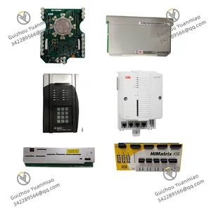
ABB 3BHB000582P201 Multifunction Controller Module
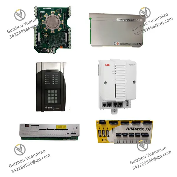
ABB 3BHB000582P201 Multifunction Controller Module photo-1

Negotiable MOQ: 1 Piece (Price negotiable depending on order volume and customization)
Key Specifications
Get Latest Price
Material:
Other, Global universal model
Condition:
Other, Global universal model
Task:
Other, Global universal model
Payment & Shipping
Payment Methods:
Port of Shipment:
guizhou
Delivery Detail:
Delivery time depends on order quantity.
Material Other, Global universal model
Condition Other, Global universal model
Task Other, Global universal model
Mathematical Model Other, Global universal model
Signal Other, Global universal model
Customized Non-Customized
Structure Other, Global universal model
Operating Temperature -20℃ ~ 60℃
Relative Humidity 5%-95% (non-condensing)
Dimensions 150mm × 80mm × 60mm

I. Overview


ABB 3BHB000582P201 is a high-performance distributed I/O module, serving as a core signal acquisition and transmission component of industrial automation control systems. Specifically designed for complex industrial scenarios in industries such as metallurgy, chemical engineering, electric power, and intelligent manufacturing, it undertakes key tasks including on-site sensor signal acquisition, actuator control command output, equipment status monitoring, and data transmission. As a "bridge" connecting on-site equipment and control systems, this module can accurately convert analog signals (such as temperature, pressure, and flow) and digital signals (such as switch and liquid level) into standardized industrial signals, upload them to upper-level control systems like PLC and DCS, and simultaneously receive upper-level commands to drive the actions of on-site actuators, thereby realizing precise control of industrial production processes.


With its modular architecture and strong environmental adaptability, the 3BHB000582P201 module is compatible with industrial control systems of different scales and is widely used in scenarios such as large-scale production lines, smart factories, and process control workshops. It not only features high-precision signal acquisition and transmission performance but also effectively copes with complex working conditions in industrial sites, such as electromagnetic interference and temperature-humidity fluctuations, through technologies like redundancy design and anti-interference enhancement, ensuring the stability and reliability of data transmission. Meanwhile, the module supports hot-swapping and rapid configuration, enabling flexible expansion of the number of I/O channels to meet the needs of production line upgrading and transformation, thus providing core signal processing support for the efficient operation of industrial automation systems.


II. Technical Parameters


Parameter Category Specific Specifications Detailed Description
Power Supply Parameters Operating Power Input DC 24V ±15%, allowing short-term fluctuation range: 20.4V ~ 27.6V; equipped with reverse power connection protection, overvoltage protection (triggered when ≥30V), and undervoltage protection (triggered when ≤19V) functions.

Power Consumption Indicator No-load power consumption ≤ 3W; full-load operation power consumption ≤ 12W; single-channel signal acquisition power consumption ≤ 0.5W.


Signal Acquisition Parameters

Analog Input


8-channel differential analog input, supporting 4~20mA DC current signals or 0~10V DC voltage signals; signal type can be switched via configuration software; input impedance: ≥250Ω for current signals, ≥100kΩ for voltage signals.


Analog Acquisition Accuracy Current signal: ±0.1% FS; Voltage signal: ±0.2% FS; Sampling rate: 100Hz per channel, supporting multi-channel synchronous sampling.

Digital Input 16-channel digital input, supporting dry contact/wet contact input; input voltage range for wet contact: 18~30V DC; response time ≤ 1ms.

Signal Filtering Built-in programmable digital filtering function; filter time constant adjustable from 1ms to 100ms, effectively suppressing high-frequency interference signals.


Control Output Parameters

Analog Output


4-channel analog output, supporting 4~20mA DC current signals or 0~10V DC voltage signals; signal type can be switched via configuration; output load: ≤500Ω for current signals, ≥1kΩ for voltage signals.


Digital Output 8-channel digital output, adopting relay output; contact rating: 2A/250V AC or 2A/30V DC; supporting normally open/normally closed contact configuration.


Communication Parameters


Interface Type


1 PROFINET interface (RJ45), 1 RS485 interface (terminal type), supporting bus redundancy configuration.


Supported Protocols PROFINET V2.3, Modbus-RTU protocols; Communication rate: up to 100Mbps for PROFINET, configurable 9600~115200bps for RS485.


Environmental Parameters


Temperature & Humidity Range


Operating temperature: -20℃ ~ 60℃; Storage temperature: -40℃ ~ 85℃; Relative humidity: 5% ~ 95% (non-condensing).


Anti-interference & Protection Complies with IEC 61000-4 anti-interference standards; ESD contact discharge ±8kV, air discharge ±15kV, surge immunity ±2kV; Protection class IP67, supporting direct on-site installation.
Physical Parameters


Dimensions & Installation


150mm × 80mm × 60mm (length × width × height); installed via DIN 35mm standard guide rail or screw fixing, supporting hot-swapping; recommended module spacing ≥ 15mm.


III. Functional Features


1. High-Precision Multi-Type Signal Acquisition and Output

The module integrates 8-channel analog input, 16-channel digital input, 4-channel analog output, and 8-channel digital output, which can fully cover common signal types in industrial sites. For analog acquisition, a 16-bit high-precision ADC chip is used, with an acquisition accuracy of ±0.1% FS for current signals and ±0.2% FS for voltage signals. It supports multi-channel synchronous sampling to ensure accurate acquisition of key parameters such as temperature and pressure. For analog output, a 14-bit DAC chip is adopted, featuring high output signal stability and the ability to accurately drive actuators like control valves and frequency converters. The digital input has a response time of ≤1ms, enabling rapid capture of switch state changes; the digital relay output has a large load-driving capacity, suitable for various devices such as solenoid valves and indicator lights.


2. Strong Anti-Interference and Adaptability to Harsh Environments

It adopts an enhanced electromagnetic compatibility design, with core circuits using differential signal transmission and optocoupler isolation technologies. Having passed all anti-interference tests of IEC 61000-4, it can effectively resist complex interferences in industrial sites, such as electromagnetic radiation, voltage surges, and burst pulses, ensuring the stability of signal transmission. With a protection class of IP67, it is dustproof and splash-proof, allowing direct installation in on-site environments like production workshops and beside equipment without the need for dedicated control cabinets, thus reducing installation costs. Its operating temperature range covers -20℃ to 60℃, enabling adaptation to extreme environments such as workshops in cold regions and high-temperature production workshops, and meeting on-site installation needs of different industries.


3. Flexible Communication and Bus Redundancy Guarantee

Equipped with dual communication interfaces (PROFINET and RS485), it supports mainstream industrial bus protocols such as PROFINET V2.3 and Modbus-RTU. It can be seamlessly connected to PLC and DCS control systems of brands like Siemens and ABB, realizing high-speed data interaction with upper-level systems. The PROFINET interface has a maximum communication rate of 100Mbps, supporting control scenarios with high real-time requirements; the RS485 interface can be used for long-distance data transmission, with a maximum transmission distance of 1200m. It supports bus redundancy configuration—when the main communication link fails, it automatically switches to the backup link, with a switching time of ≤10ms, ensuring uninterrupted data transmission and improving system reliability.


4. Hot-Swapping and Convenient Configuration & Maintenance

It supports the hot-swapping function for modules, allowing installation and replacement of modules without shutting down the system. This avoids production line downtime caused by module maintenance and improves production efficiency. It is equipped with dedicated configuration software that supports graphical interface operation, enabling quick completion of functions such as signal type switching, filtering parameter setting, and channel address configuration without complex programming. The module has a built-in self-diagnosis function, which can real-time monitor information such as power supply status, communication status, and channel faults, and upload fault codes via the communication interface. Maintenance personnel can quickly locate fault positions through the upper-level system. Status indicators are provided on the module surface, intuitively displaying the operating status of the power supply, communication, and channels, facilitating rapid on-site troubleshooting.


5. Modular Expansion and Safety Design

Adopting a standardized modular design, it supports cascading expansion of multiple modules. The number of modules can be flexibly increased or decreased according to on-site I/O channel requirements, with a maximum of 32 cascaded modules. This makes it compatible with control systems of different scales, from small equipment to large-scale production lines. The power input is equipped with reverse connection protection, overvoltage protection, and undervoltage protection functions. When the input power supply is abnormal, the module automatically cuts off the power supply or issues an alarm to avoid module damage. The digital output adopts a short-circuit protection design—when the output circuit is short-circuited, it automatically provides current-limiting protection and can recover automatically after the fault is eliminated, extending the service life of the equipment.


IV. Common Faults and Solutions


Common Faults Possible Causes Solutions
Module fails to power on, power indicator not lit 1. Loose power terminal blocks or incorrect wiring; 2. Input voltage beyond the range of 20.4~27.6V; 3. Faulty power module or blown internal fuse; 4. Protection triggered due to reverse power connection.
  1. Check the power wiring, tighten the terminal blocks, and ensure correct positive and negative polarity wiring; 2. Measure the input voltage with a multimeter; repair the power supply circuit or install a voltage stabilizer if abnormal; 3. After power-off, check the fuse (specification: 1A/250V) and replace it if blown; send the faulty power module back to the factory for repair; 4. Swap the positive and negative wires of the power supply, confirm correct wiring, and then power on again.


Excessive deviation of analog acquisition data 1. Loose sensor wiring or damaged signal cables; 2. Incorrect signal type configuration (wrong current/voltage switching); 3. Unreasonable filtering parameter settings; 4. Expired calibration of module channels; 5. Severe on-site electromagnetic interference.
  1. Tighten the sensor wiring, replace damaged cables, and use shielded cables to reduce interference; 2. Verify the signal type configuration via the configuration software to ensure consistency with the sensor output; 3. Adjust the filter time constant (5~20ms recommended) to balance accuracy and response speed; 4. Recalibrate the module channels using a standard signal source; 5. Check the grounding of shielded cables to ensure single-point grounding, and install a signal isolator.


Communication interruption, unable to interact with upper-level system 1. Incorrect communication wiring (TX/RX reversed or poorly made network cable connectors); 2. Mismatched communication parameters (IP address, baud rate, station number); 3. Damaged communication interface or excessive bus load; 4. Faulty communication port of the upper-level system; 5. Communication packet loss caused by electromagnetic interference.
  1. Check the wiring diagram to adjust the communication wiring, remake the network cable connectors, and test continuity; 2. Unify the communication parameters of the module and the upper-level system to ensure consistent protocols; 3. Replace with a backup communication interface and reduce the number of bus modules (maximum 32 modules per bus); 4. Check the communication port of the upper-level system, restart the system, or replace the port; 5. Use shielded communication cables and ensure reliable grounding, shorten the communication distance, or install a repeater.


No digital output action, load not working 1. Loose output terminal wiring or short-circuited load; 2. Incorrect output channel configuration (wrong normally open/normally closed setting); 3. Damaged relay output contacts; 4. Load power exceeding the module's output capacity; 5. Faulty internal drive circuit of the module.
  1. Tighten the output terminal wiring, use a multimeter to test the continuity of the load circuit, and eliminate short-circuit faults; 2. Check the output channel configuration via the configuration software and adjust the normally open/normally closed settings; 3. Replace with a backup output channel for testing; if the contacts are confirmed damaged, send the module back to the factory for repair; 4. Verify the load power to ensure it does not exceed the 2A/250V AC specification; install a power amplifier if necessary; 5. Replace the module for testing; if the drive circuit is confirmed faulty, send the module back to the factory for repair.


Module fails to work normally after hot-swapping 1. Poor contact during hot-swapping; 2. Compatibility issues between the module and the bus; 3. Upper-level system fails to re-identify the module; 4. Outdated module firmware version. 1. Power off, reinsert the module, and ensure the module is installed in place; 2. Confirm the compatibility between the module model and the bus system, and refer to the compatibility manual; 3. Refresh the bus device list through the upper-level system to re-identify the module; 4. Upgrade the module firmware to the latest version via the configuration software.
Product Tags: 3BHB000582P201

Send Inquiry to This Supplier

* Message
0/5000

Want the best price? Post an RFQ now!
Verified Business License
Business Type
Trading Company
Year Established
2014
Factory Size
1,000-3,000 square meters
Product Certifications
SA8000

