



Home > Electrical & Electronics > Electrical Control System > ABB GVC707AE01 3BHB003149P104 Thyristor Module
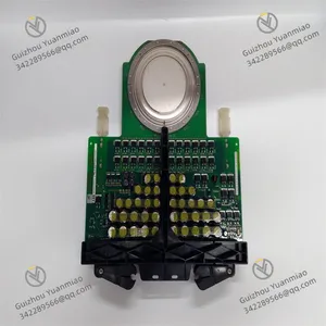
ABB GVC707AE01 3BHB003149P104 Thyristor Module
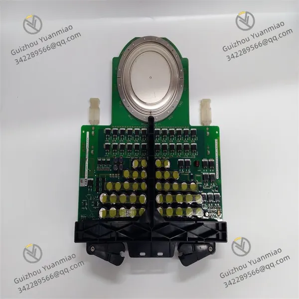
ABB GVC707AE01 3BHB003149P104 Thyristor Module photo-1

Negotiable MOQ: 1 Piece (Price negotiable depending on order volume and customization)
Key Specifications
Get Latest Price
Material:
Other, Global universal model
Condition:
Other, Global universal model
Task:
Other, Global universal model
Payment & Shipping
Payment Methods:
Port of Shipment:
guizhou
Delivery Detail:
Delivery time depends on order quantity.
Material Other, Global universal model
Condition Other, Global universal model
Task Other, Global universal model
Mathematical Model Other, Global universal model
Signal Other, Global universal model
Customized Non-Customized
Structure Other, Global universal model
Operating Temperature -10℃ ~ 65℃
Relative Humidity 5%-95% (non-condensing)
Dimensions 280mm × 220mm × 80mm

I. Overview


ABB GVC707AE01 3BHB003149P104 is a high-end industrial frequency converter control module, which serves as the core control unit of medium and high-voltage frequency converters. Specifically designed for speed control of high-power asynchronous or synchronous motors in industries such as metallurgy, mining, electric power, and cement, it undertakes key tasks including precise adjustment of motor speed, real-time monitoring of operating status, fault diagnosis and protection, and system communication interaction. As the "brain" that enables the frequency converter to achieve efficient speed regulation, this module accurately controls the torque and speed of the motor through advanced vector control algorithms. It is suitable for various heavy-load or light-load scenarios such as fans, pumps, crushers, and conveyors, realizing energy-efficient operation of the motor and precise control of the process.


With its excellent control performance and high-reliability design, the GVC707AE01 3BHB003149P104 module is compatible with medium and high-voltage frequency converters with a voltage level of 3kV~10kV and a power range of 100kW~2000kW. It is widely used in the drive systems of key equipment such as large industrial production lines, mining equipment, power plant fans and pumps, and cement rotary kilns. It not only features high-precision speed regulation performance and fast dynamic response capability but also effectively copes with complex working conditions such as strong electromagnetic interference and voltage fluctuations in industrial sites through multiple redundancy designs and enhanced anti-interference technologies, ensuring the safe and stable operation of the frequency converter and the motor. At the same time, the module supports seamless connection with upper-level control systems such as factory DCS and SCADA, enabling remote equipment monitoring, remote parameter setting, and operation and maintenance data tracing, thus providing core control support for the intelligent and efficient operation of industrial production.


II. Technical Parameters


Parameter Category Specific Specifications Detailed Description
Power Supply Parameters Control Power Input DC 24V ±10%, allowing a short-term fluctuation range of 21.6V ~ 26.4V; equipped with reverse power connection protection, overvoltage protection (triggered when ≥28V), and undervoltage protection (triggered when ≤19V) functions.

Power Consumption Indicator Power consumption in normal operation ≤ 40W; power consumption during speed regulation dynamic process ≤ 60W; standby power consumption ≤ 12W.


Control Performance Parameters


Motor Type Compatibility


Three-phase asynchronous motor, synchronous motor; supports sensorless control of permanent magnet synchronous motors.


Control Algorithms Vector Control (FOC), Direct Torque Control (DTC), V/F Control; supports undisturbed algorithm switching.

Speed Regulation Accuracy In vector control mode: speed accuracy ±0.01% of rated speed; speed range 0.01~100Hz (expandable to 150Hz).

Dynamic Response Torque step response time ≤ 10ms; speed step response overshoot ≤ 3%, recovery time ≤ 50ms.


I/O Parameters


Analog Input/Output


8-channel analog input (4~20mA DC or 0~10V DC, configurable); 4-channel analog output (4~20mA DC, accuracy ±0.1% FS).


Digital I/O 24-channel digital input (dry contact/wet contact optional, wet contact 18~30V DC); 16-channel digital output (relay output 2A/250V AC or transistor output 0.5A/24V DC, configurable).


Communication Parameters


Interface Type


2 Ethernet interfaces (RJ45, supporting dual-network redundancy), 1 RS485 interface (terminal type), 1 CANopen interface.


Supported Protocols PROFINET V2.3, Modbus-TCP/RTU, IEC 61850, CANopen DS301; Ethernet communication rate 10/100Mbps auto-adaptive.


Environmental Parameters


Temperature & Humidity Range


Operating temperature: -10℃ ~ 65℃; storage temperature: -40℃ ~ 85℃; relative humidity: 5% ~ 95% (non-condensing).


Anti-interference & Protection Complies with IEC 61000-4 anti-interference standards, ESD contact discharge ±8kV, air discharge ±15kV, surge immunity ±2kV; protection class IP20, suitable for installation in frequency converter cabinets.
Physical Parameters


Dimensions & Installation


280mm × 220mm × 80mm (length × width × height); installed via DIN 35mm standard guide rail or screw fixing; recommended module spacing ≥ 30mm to ensure heat dissipation.

5SHX2645L0004 (1)


III. Functional Features


1. Multi-Algorithm High-Precision Speed Regulation for Diverse Loads

The module integrates three core algorithms: Vector Control (FOC), Direct Torque Control (DTC), and V/F Control, which can be flexibly selected according to the motor type and load characteristics. In the vector control mode, the speed accuracy reaches ±0.01% of the rated speed, enabling field-weakening speed increase and four-quadrant operation of the motor, which is suitable for scenarios with high requirements for speed control accuracy such as elevators and hoists. The direct torque control mode has a torque response time of ≤10ms, which can quickly suppress load fluctuations and is suitable for heavy-load impact loads such as crushers and rolling mills. The V/F control mode is easy to operate and suitable for light-load constant torque loads such as fans and pumps. It supports undisturbed algorithm switching—when switching control algorithms during operation, the motor speed fluctuation is ≤1% of the rated speed, ensuring the continuity of the production process.


2. Comprehensive Fault Protection and Redundancy Design

It has 18 built-in safety protection functions, covering core fault scenarios such as overcurrent, overvoltage, undervoltage, overload, motor stalling, motor overheating, ground fault, IGBT module fault, and power fault. When an abnormal working condition is detected, the module can quickly trigger protection actions (such as cutting off the output of the power unit, sending an alarm signal, or linking to shutdown) within 5ms, and record the fault type, occurrence time, and key parameters (speed, current, voltage, etc.) at the time of the fault, providing accurate data for fault diagnosis. It adopts a dual redundancy design—key control chips and power circuits are dual-backed up. When the main circuit fails, it automatically switches to the backup circuit with a switching time of ≤10ms. It supports redundant control of the frequency converter power unit, enabling N+1 redundant operation and greatly improving system reliability.


3. Abundant I/O and Multi-Protocol Communication Compatibility

It is equipped with sufficient I/O interface resources: 8-channel analog input can collect process signals such as pressure and flow to achieve closed-loop control; 4-channel analog output can output parameters such as speed and torque to display instruments; 24-channel digital input can receive on-site equipment status signals (such as emergency stop signals, limit switch signals); 16-channel digital output can drive actuators such as indicator lights and contactors. In terms of communication, it supports multiple interfaces including Ethernet, RS485, and CANopen, and is compatible with mainstream industrial protocols such as PROFINET and IEC 61850, enabling seamless connection to upper-level control systems of brands such as Siemens, ABB, and Schneider. The Ethernet interface supports dual-network redundancy—when the main communication link is interrupted, it automatically switches to the backup link with a switching time of ≤5ms, ensuring uninterrupted remote monitoring.


4. Strong Anti-Interference and Adaptability to Harsh Environments

It adopts an enhanced electromagnetic compatibility design—core circuits use optocoupler isolation and differential signal transmission technologies. Having passed all anti-interference tests of IEC 61000-4, it can effectively resist complex interferences in industrial sites such as electromagnetic radiation, voltage surges, and burst pulses, and can still operate stably in strong electromagnetic environments such as metallurgical workshops and mines. The operating temperature range covers -10℃~65℃, and it adopts an efficient heat dissipation design. The module has a built-in temperature sensor and intelligent heat dissipation control logic, which can automatically adjust the speed of the cooling fan according to the ambient temperature, making it suitable for extreme environments such as high-temperature workshops and outdoor frequency converter cabinets. The control power supply supports a wide input range of 24V DC ±10% and is equipped with reverse connection, overvoltage, and undervoltage protection to avoid module damage caused by abnormal power supply.


5. Intelligent Operation & Maintenance and Convenient Configuration Design

It is equipped with a 7-inch color touchscreen and 12 physical operation buttons. The interface adopts a multi-language menu design (supporting Chinese, English, German, French, etc.) to intuitively display operating parameters such as motor speed, current, and torque, as well as protection status. It supports dual local and remote configuration—locally, parameter setting and fault reset can be completed through the touchscreen; remotely, functions such as parameter downloading, program upgrading, and fault diagnosis can be realized through upper-level software, allowing operation and maintenance personnel to complete equipment debugging without on-site operations. It has a built-in equipment health management function that can real-time monitor the module's operating temperature, communication status, I/O interface status, etc. Through trend analysis, it predicts potential faults (such as capacitor aging and fan wear) and issues early warnings to realize predictive maintenance. It adopts a modular plug-in design—core functional modules can be disassembled and replaced independently, reducing maintenance difficulty and downtime.


6. Energy-Saving Optimization and Process Closed-Loop Control

It has a variety of energy-saving control strategies and supports frequency conversion energy-saving and power factor compensation functions. In fan and pump load scenarios, it can automatically adjust the speed according to process requirements, achieving an energy-saving rate of 20%~60% compared with traditional constant-speed operation. The power factor compensation function can make the output power factor of the frequency converter ≥0.95, reducing the reactive power loss of the power grid. It supports multi-variable closed-loop control, which can collect multiple process parameters such as speed, pressure, and flow at the same time, and realize multi-parameter coordinated control through PID adjustment algorithms, making it suitable for complex process production scenarios (such as coordinated control of speed and temperature of cement rotary kilns). It has a built-in energy-saving operation recording function that can count the daily and monthly energy-saving electricity, providing data support for enterprise energy efficiency management.


IV. Common Faults and Solutions


Common Faults Possible Causes Solutions
Module fails to start, touchscreen has no display 1. Control power not connected or terminal blocks loose; 2. Input voltage beyond the range of 21.6~26.4V; 3. Faulty power module or blown internal fuse; 4. Damaged touchscreen or communication fault.
  1. Check the control power line connection, tighten the terminal blocks, and confirm the power switch is closed; 2. Measure the input voltage with a multimeter; repair the power supply circuit or install a voltage stabilizer if abnormal; 3. After power-off, check the fuse (specification: 5A/250V) and replace it if blown; send the faulty power module back to the factory for repair; 4. Restart the module for testing; if there is still no display, replace the touchscreen or check the communication line between the touchscreen and the main board.


Excessive motor speed fluctuation 1. Improper selection of control algorithm; 2. Unreasonable PID parameter tuning; 3. Faulty speed feedback signal (e.g., loose encoder wiring); 4. Frequent sudden changes in load; 5. Excessive power supply voltage fluctuation.
  1. Replace the control algorithm according to the load type (e.g., select DTC control for heavy loads); 2. Retune the PID parameters through upper-level software to optimize the proportional and integral coefficients; 3. Check and tighten the encoder wiring, detect the feedback signal with an oscilloscope, and replace the encoder if faulty; 4. Investigate the cause of sudden load changes, install buffer devices or optimize the process; 5. Measure the power supply voltage, and install a voltage stabilizer or UPS if the fluctuation is excessive.


Module reports "overcurrent fault" 1. Short circuit or grounding of motor windings; 2. Damaged IGBT module of the power unit; 3. Load overload (exceeding 150% of rated load); 4. Faulty current sampling circuit; 5. Incorrect parameter setting of the control algorithm.
  1. After power-off, use an insulation resistance tester to detect the insulation resistance of the motor windings; repair the motor if there is a short circuit or grounding; 2. Check the IGBT module of the power unit, measure the conductivity with a multimeter, and replace it if damaged; 3. Verify the load power, reduce the load or replace with a frequency converter of higher power if the rated load is exceeded; 4. Check the current sensor and sampling line, repair or replace if faulty; 5. Restore the default parameters of the control algorithm and re-debug.


Communication interruption, unable to perform remote monitoring 1. Incorrect communication wiring (e.g., wrong Ethernet cable sequence, reversed RS485 TX/RX); 2. Mismatched communication parameters (IP address, baud rate, protocol type); 3. Damaged communication interface or broken network cable; 4. Firewall restrictions or port occupation of the upper-level system; 5. Communication packet loss caused by electromagnetic interference.
  1. Check the wiring standard to adjust the communication wiring (Ethernet adopts the 568B standard, RS485 distinguishes between positive and negative poles); 2. Unify the communication parameters of the module and the upper-level system to ensure consistent protocols; 3. Use a cable tester to detect the continuity of the network cable, replace the damaged network cable or test the backup communication interface; 4. Turn off the relevant firewall restrictions of the upper-level system and release the occupied port; 5. Use shielded communication cables and ensure reliable grounding, and install a communication isolator.


Motor unable to achieve four-quadrant operation 1. Vector control mode not selected for the control algorithm; 2. Incorrect parameter setting for motor forward/reverse rotation; 3. Faulty braking circuit of the power unit; 4. Damaged braking resistor or braking unit; 5. Outdated module firmware version. 1. Enter the module parameter interface and switch the control algorithm to vector control; 2. Verify the forward/reverse logic parameters to ensure the forward/reverse signals are consistent with the motor rotation direction; 3. Check the braking circuit wiring, tighten the terminal blocks, and detect the circuit continuity; 4. Measure the resistance value of the braking resistor and replace it if damaged; detect the output voltage of the braking unit and repair if faulty; 5. Upgrade the module firmware to the latest version through the communication interface.
Product Tags: GVC707AE01 , 3BHB003149P104

Send Inquiry to This Supplier

* Message
0/5000

Want the best price? Post an RFQ now!
Verified Business License
Business Type
Trading Company
Year Established
2014
Factory Size
1,000-3,000 square meters
Product Certifications
SA8000

