








 Contact Platform Support
 Help Center
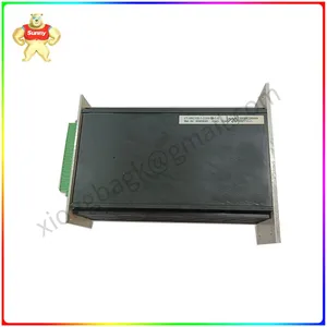
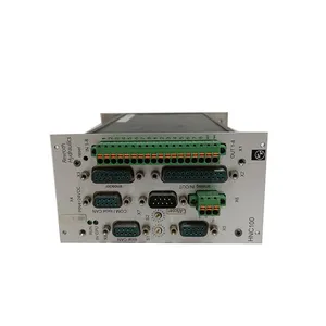
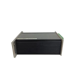
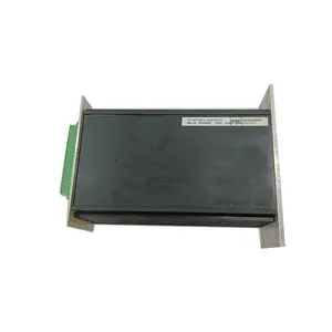
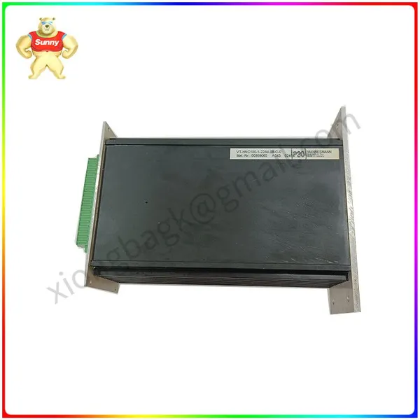
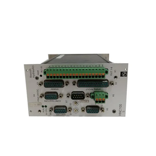
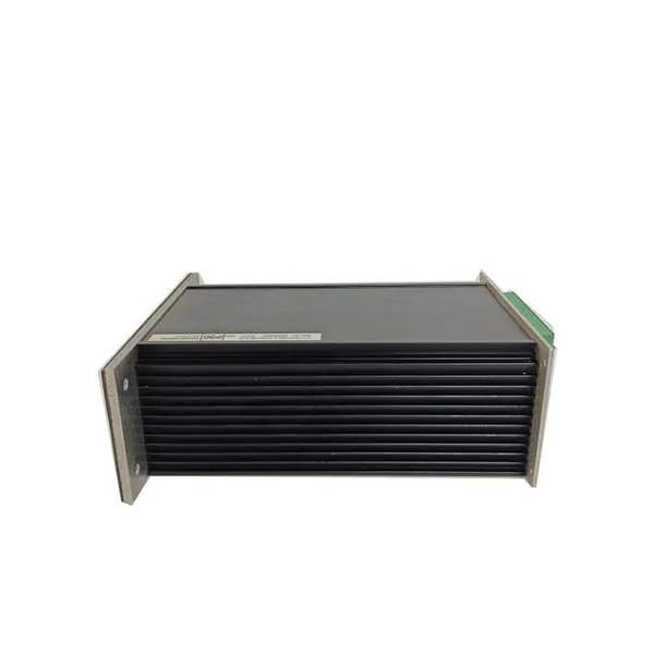
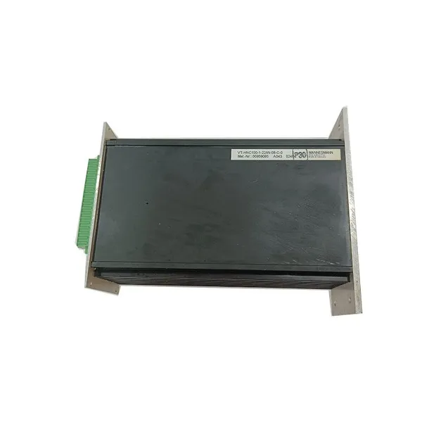
VT-HNC100-1-23/W-08-C-0 R900959000 Rexroth Controller /Amplifier


Related Products
-
 VT-HNC100-1-23W-08-P-0 VT-HNC100 Digital Axis Controllers Indramat ControlsUS$ 5278.00MOQ: 1 Pallet
 -
Rexroth MSK030C-0900-NN-M1-UG1-NNNN (R911308684) – High-Performance IndraDyn S Servo Motor for Compact, Precise MotionUS$ 3216.00MOQ: 1 Blade
-
Bosch Rexroth MSK040C-0600-NN-M1-UG1-NNNN – High‑Torque IndraDyn S Servo Motor for Compact, Fast AxesUS$ 3216.00MOQ: 1 Blade
-
Bosch Rexroth SYHNC100-NIB-23/W-24-P-D-E23-A012 Heavy‑Duty Digital Axis Controller for Hydraulic MotionUS$ 3216.00MOQ: 1 Blade
-
Rexroth Indramat DKS01.1-W030B-DL05-00 AC Servo Drive – Reliable 30 A Axis Control for Fast, Precise MotionUS$ 2216.00MOQ: 1 Blade
Technical Manual of VT-HNC100-1-23/W-08-C-0 Digital Axis Controller (Simplified Version)
Based on the general technical documents of the Bosch Rexroth VT-HNC100 series products and the derivative version materials of the same model, this article integrates and generates the core technical information of VT-HNC100-1-23/W-08-C-0, which is suitable for reference in equipment selection, installation and commissioning, and operation and maintenance. The complete official manual is recommended to be obtained through the Bosch Rexroth official website or authorized dealers.
Product Overview and Model Analysis
Basic positioning
The VT-HNC100-1-23/W-08-C-0 is a single-axis digital hydraulic shaft controller launched by Bosch Rexroth, specifically designed for closed-loop control in high-precision hydraulic drive systems. It is widely used in industrial scenarios such as injection molding machines, machine tools, and metallurgical equipment that require precise position/pressure control. This controller supports real-time data processing and multi-protocol communication, enabling dynamic response optimization of hydraulic actuators.
Model coding rules
Parse the key features of the product through the model field (based on the general coding logic of the VT-HNC100 series) :
VT-HNC100: Product Series Identification (Digital Axis Controller)
1: Axis configuration (1 = single axis; 2 = dual axes)
23: Component Series Number (Hardware version identifier)
W: Installation form (W = Wall-mounted shell)
08: Digital I/O quantity (8=8 channels of digital input/output)
C: Bus type (speculated to be CANopen, please refer to the official documentation for accuracy)
0: Special Function Code (Basic Configuration)
Core technical parameters
Electrical specifications
Supply voltage: 18-36VDC (24VDC is recommended)
Power consumption: Typical value 15W, maximum value 20W
Digital I/O: 8-channel bidirectional digital input/output (24V level, maximum load current 200mA)
Analog interface
Input: 4-channel differential analog input (±10V range, 12-bit resolution
Output: 2 analog outputs (±10V or 0-20mA selectable)
Communication interface
Main bus: CANopen (Speculation, needs to be confirmed in combination with actual wiring)
Local CAN: Supports CAN_H/CAN_L differential transmission
Advanced control interface: Supports PROFIBUS DP or INTERBUS-S (requires configuration via X5 interface)
Environmental parameters
Operating temperature: 0-55℃ (external temperature of the shell)
Storage temperature: -20-70℃
Protection grade: IP20 (housing)
Anti-vibration: 10-500Hz, amplitude 0.15mm (peak)
Impact resistance: 15g acceleration (11ms duration)
Control performance
Control cycle: Minimum 1ms (position control mode)
Position control accuracy: ±0.01mm (depending on the resolution of the feedback device)
Supported feedback types: incremental encoder, SSI absolute value encoder
Control modes: Position control, pressure control, speed control (can be switched through software)
Hardware structure and wiring instructions
Interface layout
The main interfaces of the controller are concentrated on the front panel. The key interfaces are defined as follows (based on the general pin configuration of the VT-HNC100 series) :
Interface identifier Function description Key pin definitions
X1 Digital I/O interface 1-4: IN1-IN4 (digital input) 5-8: OUT1-OUT4 (Digital output)
X2 Analog Interface 1: Uin1+ (Positive analog input 1) 2: Uin1- (Analog input 1 negative); 12: Uref=+10V (reference voltage); 13: Uref=-10V; 14: Iout1 (Analog Output 1); 15: Uout1 (Analog Output 1)
The X3 encoder interface supports incremental encoders (UB0/UB1/UB2 signals) and SSI absolute encoders (data/clock signals)
The X5 advanced communication interface supports PROFIBUS DP or INTERBUS-S. Pins 1 to 9 include RxD/TxD, power and ground pins
X8 Local CAN interface 1: CAN_GND; 8: CAN_H; 9: CAN_L
The X6 power interface is shielded and grounded. Positive pole (18-36VDC); Negative pole (GND
Wiring precautions
Grounding requirements: The shielded wire must be grounded at one end (it is recommended to ground on the controller side) to avoid forming a ground loop
CAN bus wiring: CAN_H (X8-8) and CAN_L (X8-9) need to use twisted-pair cables, and 120Ω terminal resistors should be connected at both ends of the bus
Reserved pins: Pins marked "res" (such as pins 2 to 6 of X8) must be left unconnected and not connected
Power protection: It is recommended to connect a 10A fuse in series at the power input end to prevent overcurrent damage
Installation and commissioning
Installation specifications
Installation method: Wall-mounted installation (requires M4 screws for fixation, installation surface flatness ≤0.1mm)
Installation spacing: Reserve at least 50mm of heat dissipation space around the controller (top and side)
Wiring requirements: Power lines and signal lines should be laid separately (with a spacing of ≥100mm), and shielded wires should be used for analog lines
Debugging process
Hardware check
Confirm that the power supply voltage meets the requirements
Check the correctness of all interface wiring (especially grounding and CAN bus terminal resistance)
Software configuration
Install and debug the software Win-PEd®6/7 (available for download from the official website of Bosch Rexroth)
Connect the controller to the computer via a USB or CAN interface
Load the default configuration file and modify the control parameters (such as proportional gain and integration time) according to the application requirements
Functional test
Digital I/O testing: By forcing output signals through software, verify the actions of external actuators
Analog quantity calibration: Calibrate the analog input accuracy using a standard signal source
Closed-loop test: Connect the feedback device and conduct position tracking test (it is recommended to start from low gain and gradually optimize)

Send Inquiry to This Supplier



You May Also Like
-
Rexroth PPC-R22.1N-T-Q2-G2-NN-FW – Multi‑Axis Motion and Machine Control for Demanding LinesUS$ 2216.00MOQ: 1 Blade
-
REXROTH FCS01.1E-W0011-A-04-NNBV High‑Efficiency AC Frequency Converter – Energy‑Saving Speed Control for 3‑Phase MotorsUS$ 3216.00MOQ: 1 Blade
-
REXRTOH SYHNC100-NIB-22a/W-24-P-D-E24: The Axis Controller That Keeps Your Production Line Breathing at 3 AMUS$ 236.00MOQ: 1 Blade
-
Bosch Rexroth HMV01.1R-W0018-A-07-FNN1: Precision Hydraulic Valve Control ModuleUS$ 236.00MOQ: 1 Blade
-
Rexroth VTS0234-47/AP025: High-Speed Servo Drive for Precision Motion ControlUS$ 236.00MOQ: 1 Blade
-
Bosch Rexroth MSK061C-0300-NN-S1-UG0-NNNN: Your Go-To Compact Servo Motor for Tight SpacesUS$ 236.00MOQ: 1 Blade
-
Rexroth DKC11.1-040-7-FW: Your Workhorse for Demanding Motion Control TasksUS$ 236.00MOQ: 1 Blade
-
REXRTOH SYHNC100-NIB-2X/W-24-P-D-E23-A012: Precision Motion Control for Demanding Industrial LinesUS$ 236.00MOQ: 1 Blade
-
Rexroth PPC-R22.1N-N-Q1-NN-NN-FW: Precision Motion Control for Demanding Industrial ApplicationsUS$ 236.00MOQ: 1 Blade
-
Bosch Rexroth 4WRSE10V80-32: Precision Hydraulic Flow Control for Demanding Industrial SystemsUS$ 236.00MOQ: 1 Blade


