



Home > Electrical & Electronics > Electrical Control System > Honeywell CC-TUI041 Analog Input Module

Honeywell CC-TUI041 Analog Input Module
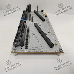
Honeywell CC-TUI041 Analog Input Module photo-1
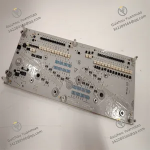
Honeywell CC-TUI041 Analog Input Module photo-2
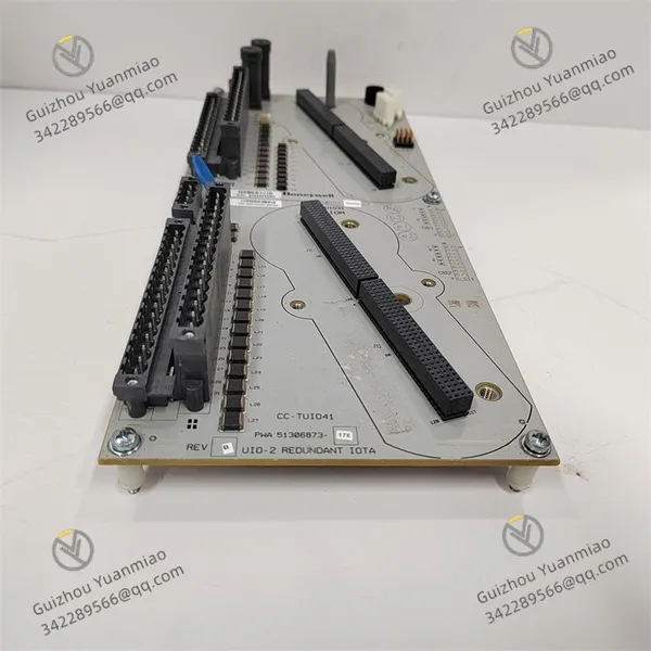
Negotiable MOQ: 1 Piece (Price negotiable depending on order volume and customization)
Key Specifications
Get Latest Price
Material:
Other, Global universal model
Condition:
Other, Global universal model
Task:
Other, Global universal model

Payment & Shipping
Payment Methods:
Port of Shipment:
China
Delivery Detail:
Delivery time depends on order quantity.
Material Other, Global universal model
Condition Other, Global universal model
Task Other, Global universal model
Mathematical Model Other, Global universal model
Signal Other, Global universal model
Customized Non-Customized
Structure Other, Global universal model
Operating Temperature -40℃~70℃
Storage Temperature -40℃~85℃

I. Product Overview


The Honeywell CC-TUI041 is a universal Input/Output (I/O) module in distributed control systems. As a core hardware component connecting on-site equipment and the control layer, it undertakes the dual-directional interaction of industrial signals—it not only accurately collects analog/digital signals from on-site sensors and transmitters but also converts logical commands issued by the control system into control signals recognizable by actuators. It is a key component ensuring the stable, safe, and efficient operation of industrial processes.


In modern industrial production, reliable signal interaction is essential for tasks ranging from regulating reaction parameters in large-scale chemical plants, monitoring unit status in power plants, to controlling precision processes in manufacturing production lines. With its flexible channel configuration, strong anti-interference capability, and wide environmental adaptability, the CC-TUI041 can be adapted to multiple types of industrial scenarios. It is particularly suitable for control requirements with dense sensors and complex signal types, such as multi-parameter monitoring (temperature/pressure/liquid level) of chemical reactors and cluster control of valves in oil refineries. It provides efficient on-site data support and command execution capabilities for the Experion PKS system.


CC-TUI041 (2)


II. Technical Specifications and Performance


  1. Signal Processing and Channel Configuration


Parameter Category Specific Specifications
Channel Configuration 16 configurable I/O channels, supporting independent switching between Analog Input (AI), Analog Output (AO), Digital Input (DI), and Digital Output (DO) modes (4 channels per group, with uniform mode within each group)
Analog Signal Support Input: 4-20mA DC (default), 0-20mA DC, 1-5V DC, 0-5V DC; Output: 4-20mA DC (load resistance ≤ 500Ω), 0-20mA DC
Digital Signal Support Input: Dry contact/wet contact (24V DC), response time ≤ 1ms; Output: Relay output (dry contact, normally open/normally closed configurable, rated current 2A@250V AC)
Measurement Accuracy Analog Input: ±0.1% FS (4-20mA/1-5V); Analog Output: ±0.2% FS (4-20mA)
Sampling Rate Maximum 10Hz per analog input channel, maximum 100Hz per digital input channel, no delay in channel switching


2. Electrical and Safety Features

  • Isolation Protection: Adopts a triple isolation design—inter-channel isolation voltage ≥ 250Vrms, isolation voltage between input/output and backplane ≥ 500Vrms, and independent isolation between analog and digital circuits. This effectively blocks common-mode interference (e.g., 1kV common-mode voltage generated by frequency converters) and ground loops in industrial sites, ensuring signal stability even in electromagnetic environments with dense high-power equipment (such as rolling mill workshops in steel plants).

  • Overvoltage and Overcurrent Protection: Analog channels are equipped with built-in overvoltage protection (maximum withstand voltage ±30V DC) and current-limiting components (30mA current limit for analog output). Digital output channels have short-circuit protection (automatically cuts off output in case of overload and self-recovers after fault resolution), preventing module damage caused by on-site wiring errors or equipment failures.

  • Redundant Power Supply: Supports 24V DC redundant power supply (operating voltage range 18-32V DC) and maintains stable operation during power fluctuations. It is equipped with a power fault detection function, which uploads alarm information via the bus when abnormalities occur, improving system fault tolerance.


3. Environmental and Reliability Indicators

  • Wide Temperature Operating Range: -40℃~70℃ (operation), -40℃~85℃ (storage). It is suitable for extreme scenarios such as outdoor control cabinets in frigid zones and high-temperature chemical workshops, without the need for additional temperature control equipment.

  • Harsh Environment Resistance: IP20 protection rating (module itself), relative humidity 5%~95% (non-condensing). The board surface is coated with a conformal coating (thickness ≥ 0.1mm), which can resist dust, moisture, and mild chemical corrosion (e.g., high-salt-fog coastal environments).

  • Mean Time Between Failures (MTBF): ≥ 150,000 hours. Key components (such as ADC chips and relays) use industrial-grade long-life devices, reducing maintenance frequency and downtime risks.


4. Communication and System Integration

  • Bus Interface: Communicates with the controller via the dedicated High-Speed Redundant (HSR) bus of the Experion PKS system, with a data transmission rate of 100Mbps. It supports real-time data refresh (cycle ≤ 100ms) and remote configuration. The controller can modify module parameters and reset faults via the bus.

  • System Compatibility: Seamlessly integrates with Experion PKS systems of version R400 and above, and supports linkage with Honeywell Control Builder software and Operator Station workstations. Channel modes, ranges, and alarm thresholds can be configured visually in Control Builder without on-site hardware adjustments.

  • Diagnostic Function: Built-in channel-level fault diagnosis—supports open-circuit/short-circuit detection for analog channels, contact sticking detection for digital channels, and fault detection for ADC/DAC chips. The fault response time is ≤ 100ms, and fault information (including channel number and type, e.g., "AI CH5 Open Circuit") is uploaded to the monitoring system in real time via the bus.


CC-TUI041 (1)


III. Installation and Maintenance


  1. Installation Specifications


(1) Rack Mounting (Experion PKS I/O Rack)

  • Tool Preparation: Phillips screwdriver (PH2), 4 M3 screws, ESD anti-static wristband (ground resistance ≤ 1MΩ);

  • Anti-static Operation: Wear the wristband and confirm proper grounding, take out the module from the anti-static packaging, and avoid touching the golden fingers and terminals;

  • Insertion and Fixing: Align the module with the 3U slot of the I/O rack, push it smoothly along the guide rail to ensure the bottom golden fingers are fully in contact with the backplane. After hearing a "click" sound, fasten the side of the module with M3 screws (torque 1.2N・m). The front panel of the module must be flush with the rack without inclination;

  • Space Reservation: Reserve ≥ 30mm heat dissipation space on both sides of the module, and avoid placing it adjacent to heat-generating components (such as power modules) to ensure effective natural heat dissipation.


(2) Wiring Operation (Taking Analog Input/Output as Examples)Analog Input (4-20mA Pressure Transmitter)

  • After confirming power-off, identify the terminal labels: "AI-CH1+" (signal positive), "AI-CH1-" (signal negative), and "GND" (common ground);

  • Use 0.5-2.5mm² shielded wires, strip 5mm of the insulation layer, remove the oxide layer, connect to the corresponding terminals, and tighten the screws (torque 0.8N・m);

  • Ground the shield layer at one end (ground resistance ≤ 4Ω), and select the transmitter side as the grounding end to avoid ground loops caused by grounding at both ends.

Analog Output (4-20mA Valve Actuator)

  • Confirm the terminals: "AO-CH5+" (output positive) and "AO-CH5-" (output negative). Connect the "+" terminal of the actuator to "AO-CH5+" and the "-" terminal to "AO-CH5-";

  • Check the load resistance of the actuator (must be ≤ 500Ω) to avoid signal distortion caused by exceeding the module's output capacity.


2. Configuration and Maintenance


(1) Channel Configuration (Honeywell Control Builder Software)

  • Software Connection: Connect the PC to the Experion PKS controller via Ethernet, open Control Builder, and log in with an administrator account;

  • Module Recognition: In the "Hardware Configuration" interface, the system automatically recognizes the CC-PUIO31 (displays model and serial number). If not recognized, check the backplane communication;

  • Mode Setting:

    • Select the "CH1-CH4" channel group, set the mode to "AI (4-20mA)", range to "0-10MPa", and alarm thresholds to "High Alarm 8MPa, Low Alarm 2MPa";

    • Select the "CH5-CH8" channel group, set the mode to "AO (4-20mA)", and output range to "0-100% Valve Opening";

  • Configuration Application: Click "Download" to send the configuration to the module (takes approximately 5 seconds). After the software prompts "Configuration Successful", check the channel status in the "Real-Time Data" interface.


(2) Daily Maintenance

  • Status Monitoring: Check the LED indicators on the front panel of the module daily (PWR: Power Green, RUN: Operation Green, ERR: Fault Red, COMM: Communication Yellow). Under normal conditions, the PWR/RUN/COMM lights are on, and the ERR light is off. Check channel data via the workstation weekly, compare it with the actual values of on-site equipment (e.g., measure transmitter output with a multimeter), and confirm the accuracy is within the allowable range.

  • Cleaning and Calibration: Clean dust on terminals and heat sinks with compressed air (pressure ≤ 0.2MPa) every 3 months; calibrate analog channels every year (use a standard signal generator, start "Calibration Mode" in Control Builder, input 0%/50%/100% FS signals in sequence, and the system automatically corrects errors).

  • Troubleshooting: When the ERR light is on, check the fault code in the "Fault Diagnosis" interface of Control Builder (e.g., "E03" indicates CH3 Short Circuit). Locate the channel, inspect the wiring and on-site equipment, click "Fault Reset" after repair, and the ERR light will turn off.

Product Tags: Honeywell , CC-TUI041

Send Inquiry to This Supplier

* Message
0/5000

Want the best price? Post an RFQ now!
Verified Business License
Business Type
Trading Company
Year Established
2014
Factory Size
1,000-3,000 square meters
Product Certifications
SA8000


