

Home > Electrical & Electronics > Electrical Control System > Allen-Bradley 1756-OA16I Discrete AC Output Module
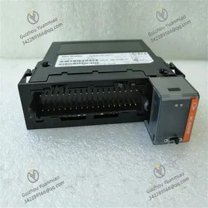
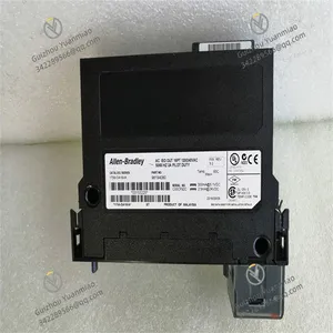
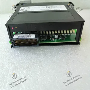
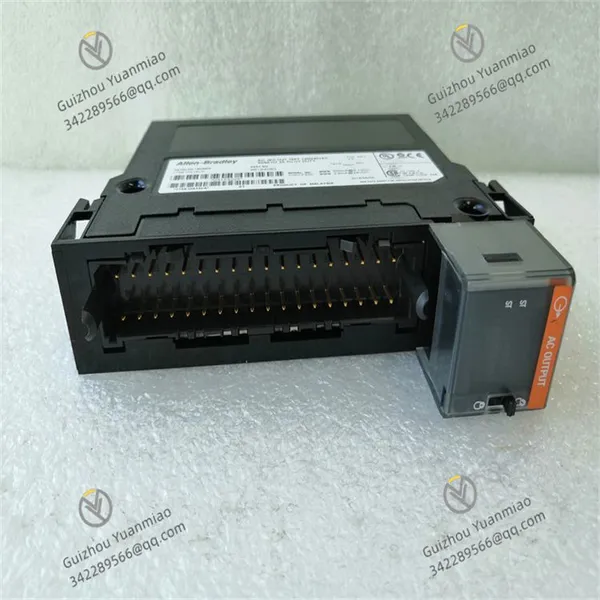
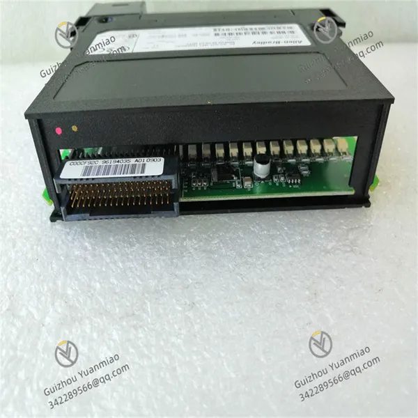
Allen-Bradley 1756-OA16I Discrete AC Output Module

Negotiable
MOQ: 1 Unit (Price negotiable depending on order volume and customization)
Key Specifications
Get Latest Price
Material:
Other, Global universal model
Condition:
Other, Global universal model
Task:
Other, Global universal model
Payment & Shipping
Payment Methods:
Port of Shipment:
China
Delivery Detail:
Delivery time depends on order quantity.
Related Products
-
 Allen-Bradley 1756-OB16E Digital I/O ModuleNegotiableMOQ: 1 Unit
 -
Allen-Bradley 1756-OB32 Discrete Output ModuleNegotiableMOQ: 1 Unit
-
Allen-Bradley 1756-OF8 ControlLogix Analog Output ModuleNegotiableMOQ: 1 Unit
-
Allen-Bradley 1756-OW16I Discrete Output ModuleNegotiableMOQ: 1 Unit
-
Allen-Bradley 1756-PA75 ControlLogix AC Power SupplyNegotiableMOQ: 1 Unit
Material
Other, Global universal model
Condition
Other, Global universal model
Task
Other, Global universal model
Mathematical Model
Other, Global universal model
Signal
Other, Global universal model
Customized
Non-Customized
Structure
Other, Global universal model
Operating temperature
0°C to 60°C
Humidity
5% - 95% (non - condensing)
Power Input
24V DC

Send Inquiry to This Supplier

* Email
Want the best price?
Post an RFQ now!

1Yr
Business Type
Trading Company
Year Established
2014
Factory Size
1,000-3,000 square meters
Product Certifications
SA8000
You May Also Like
-
Allen-Bradley 1756-PSCA2 Chassis Adapter ModuleNegotiableMOQ: 1 Unit
-
Allen-Bradley 1756-RM ControlLogix Enhanced Redundancy ModuleNegotiableMOQ: 1 Unit
-
Allen-Bradley 1756-RM2 ControlLogix Redundancy ModuleNegotiableMOQ: 1 Unit
-
Allen-Bradley 1336-BDB-SP46D Pcb Circuit BoardNegotiableMOQ: 1 Unit
-
Allen-Bradley 1336-PB-SP11A Advanced Control ModuleNegotiableMOQ: 1 Unit
-
Allen-Bradley 1336-SN-SP10A Adjustable Frequency AC DriveNegotiableMOQ: 1 Unit
-
Allen-Bradley 1404-M405A-DNT Powermonitor 3000 ModuleNegotiableMOQ: 1 Unit
-
Allen-Bradley 1715-OB8DE ControlLogix I/O ModuleNegotiableMOQ: 1 Unit
-
Allen-Bradley 1753-L32BBBM-8A Safety ControllerNegotiableMOQ: 1 Unit
-
Allen-Bradley 1761-L32AWA ControllerNegotiableMOQ: 1 Unit


