

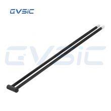
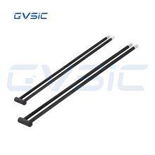
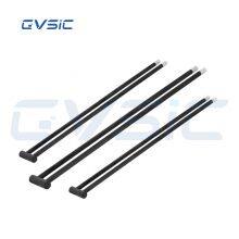
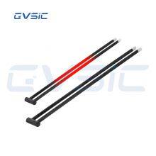
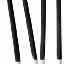
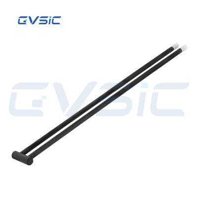
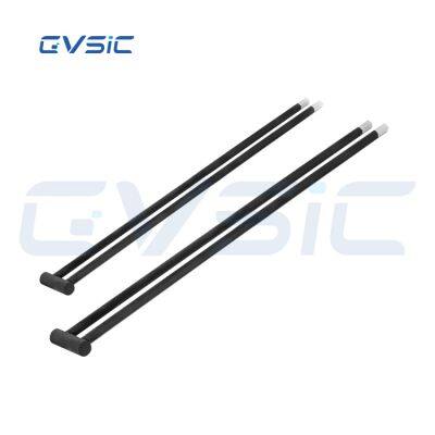
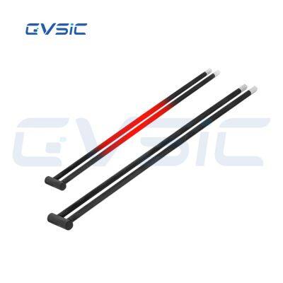
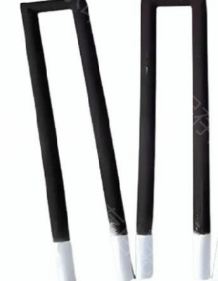
U Type SiC Heating Element

Related Products
The U-type silicon carbide rod is engineered by integrating two equal-diameter silicon carbide rods with a shared cold end, allowing power line connection at one end of the kiln. With a heating zone surface temperature of 1600°C, it is ideally suited for kilns requiring high furnace temperatures and uniform heat distribution. This design offers energy efficiency, an extended service life, and hassle-free replacement.
Also known as the GDU type, this heating element provides a reliable solution for demanding thermal applications.

| Parameter | Details |
| Material | Silicon Carbide (SiC) |
| Power Supply | Electric |
| Production Process | Crafted from premium silicon carbide blanks, enhanced through high-temperature siliconization recrystallization |
| Silicon Carbide Content | Above 99% |
| Diameter | 8-65 mm |
| Operating Temperature | Up to 1650°C |
| Voltage | 220/380V |
| Packaging | Inner cardboard box with foam padding, outer export wooden crate |
| Application | Industrial heaters/furnace heaters |
| After-sales Service | Overseas service centers available |
| Brand | Chuangwei |
When ordering a U type SiC heating element, please provide the following details:
OD: Outer diameter
HZ: Hot zone length
CZ: Cold zone length
OL: Total length
A: Handle spacing
Ordering ExampleFor instance: U type with outer diameter=20 mm, HZ=300 mm, CZ=400 mm, OL=700 mm, A=60 mm, resistance=2.24 ohms.
Designated as: U type, 20/300/700/60/2.24
All load test values in this table are measured at an element temperature of 1000°C in open air conditions, intended solely for calibration testing purposes.
| OD (mm) Diameter | HZ (mm) Hot End | CZ (mm) Cold End | A (mm) Spacing | Bridge Size | Resistance (Ω) |
| 14 | 200 | 250 | 40 | 14 | 54 |
| 14 | 250 | 300 | 50 | 14 | 64 |
| 14 | 300 | 350 | 60 | 14 | 74 |
| 16 | 200 | 250 | 40 | 16 | 56 |
| 16 | 250 | 300 | 50 | 16 | 66 |
| 16 | 300 | 350 | 60 | 16 | 76 |
| 18 | 300 | 350 | 60 | 18 | 78 |
| 18 | 400 | 400 | 70 | 18 | 88 |
| 18 | 500 | 450 | 75 | 18 | 93 |
| 20 | 250 | 300 | 50 | 20 | 70 |
| 20 | 300 | 350 | 60 | 20 | 80 |
| 20 | 400 | 400 | 70 | 20 | 90 |
| 25 | 400 | 400 | 70 | 25 | 95 |
| 25 | 500 | 450 | 75 | 25 | 100 |
| 25 | 600 | 500 | 80 | 25 | 105 |
| 30 | 600 | 400 | 70 | 30 | 100 |
| 30 | 700 | 450 | 75 | 30 | 105 |
| 30 | 800 | 500 | 80 | 30 | 110 |
Note: This table presents only a partial list of specifications. For additional sizes or custom requirements, please get in touch with us, and we will deliver tailored solutions to meet your needs.
Connection MethodThe U-type silicon carbide rod heating element operates effectively at both 220V and 380V voltages. At 220V, it is commonly configured in series or parallel connections, with series usage requiring identical resistance values for both silicon carbide rods to ensure optimal performance.
Mismatched resistance levels, whether one rod has higher resistance and the other lower resistance, can significantly reduce service life. For 380V circuits, star and delta connection methods are typically employed.
Small electric furnaces favor the star connection for its simplicity and ease of implementation, while larger furnaces utilize the delta connection. The electric furnace’s power rating generally determines the choice of connection method.
ApplicationsThe U-type silicon carbide rod heating element is predominantly used in kilns requiring single-end connections, making it an excellent choice for pusher furnaces, bogie furnaces, box furnaces, and other periodic electric furnaces.
AdvantagesCrafted from two equal-diameter silicon carbide rods sharing a single cold end, the U-type silicon carbide rod heating element allows connection at one end of the kiln. With a maximum hot zone surface temperature of 1650°C, it is tailored for high-temperature furnaces and kilns, delivering energy efficiency and an exceptionally long lifespan.
Design SuggestionsThe length of the silicon carbide rod’s heating section should match the total width of the furnace. Inserting the heating section into the furnace wall can lead to rapid erosion of the wall material.
The cold zone length should equal the furnace wall thickness plus the extension length of the freezing zone beyond the wall, typically ranging from 50 to 150 mm to facilitate secure attachment to accessories.
The furnace chamber hole diameter for the silicon carbide rod should be 1.4 to 1.6 times the cold end diameter. A hole that is too small or overly tight packing material can restrict the rod’s free expansion under continuous high temperatures, potentially causing breakage. During assembly, the rod must allow for 360-degree free rotation.
The spacing between the silicon carbide rod and the heated material or furnace wall should be at least three times the outer diameter of the heating element. In comparison, the center-to-center distance between rods should not be less than four times the outer diameter.

Send Inquiry to This Supplier

You May Also Like
-
DB Type SiC Heating ElementNegotiableMOQ: 2 Pieces
-
Straight Type SiC Heating ElementNegotiableMOQ: 2 Pieces
-
L Shape Molybdenum Disilicide RodNegotiableMOQ: 2 Pieces
-
U Shape Molybdenum Disilicide RodNegotiableMOQ: 2 Pieces
-
W Shape Molybdenum Disilicide RodNegotiableMOQ: 2 Pieces
-
I Shape Molybdenum Disilicide RodNegotiableMOQ: 2 Pieces
-
Special Shape Molybdenum Disilicide RodNegotiableMOQ: 2 Pieces
-
MoSi2 Heating Element AccessoriesNegotiableMOQ: 2 Pieces
-
Right Angle U Shaped SiC RodUS$ 0.01 - 5MOQ: 1 Piece
-
U Type SiC Heating ElementNegotiableMOQ: 2 Pieces

