

Home > Electrical & Electronics > Electrical Control System > DEIF DELOMATIC-3 Printed Circuit Board
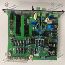
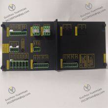
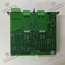
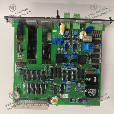
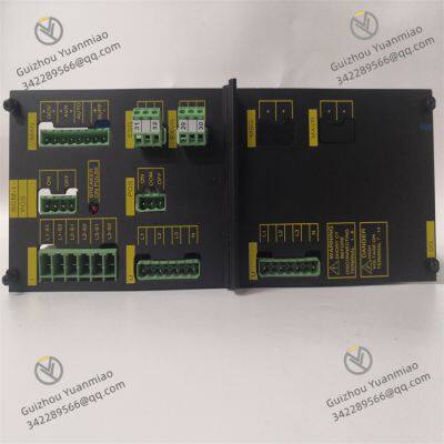
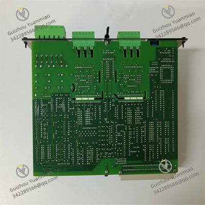
DEIF DELOMATIC-3 Printed Circuit Board
Negotiable
MOQ: 1 Piece (Price negotiable depending on order volume and customization)
Key Specifications
Get Latest Price
Material:
Other, Global universal model
Condition:
Other, Global universal model
Task:
Other, Global universal model
Payment & Shipping
Payment Methods:
Port of Shipment:
China
Delivery Detail:
Delivery time depends on order quantity.
Related Products
-
 DEIF SCM4.1 Printed Circuit BoardNegotiableMOQ: 1 Piece
 -
EATON MP3010 Motor Protection RelayNegotiableMOQ: 1 Piece
-
EATON XV-440-10TVB-1-20 Touch Screen ControllerNegotiableMOQ: 1 Piece
-
EATON XV-442-57CQB-1-10 Touch Screen ControllerNegotiableMOQ: 1 Piece
-
EATON XVS-440-10MPI-1-10 Touch Screen ControllerNegotiableMOQ: 1 Piece
Material
Other, Global universal model
Condition
Other, Global universal model
Task
Other, Global universal model
Mathematical Model
Other, Global universal model
Signal
Other, Global universal model
Customized
Non-Customized
Structure
Other, Global universal model
The DELOMATIC-3 is primarily used to detect fault conditions and trigger circuit breaker tripping to prevent damage to power equipment such as generators and transformers. It can be widely applied in industries such as power generation, marine, and industrial automation.
Functional Features
Technical Parameters
Working Principle
Common Fault Categories and Solutions
1. Unit Fails to Start
2. Unstable Voltage/Frequency
3. Communication Failures (e.g., Modbus, CANopen)
4. Overload or Short Circuit Protection Activation

Send Inquiry to This Supplier

* Email
Want the best price?
Post an RFQ now!

1Yr
Business Type
Trading Company
Year Established
2014
Factory Size
1,000-3,000 square meters
Product Certifications
SA8000
You May Also Like
-
EMG ECU01.5 ECU01 Analog Input ModuleNegotiableMOQ: 1 Piece
-
UNIOP ETT-VGA-0045 Industrial Display ModuleNegotiableMOQ: 1 Piece
-
PACIFIC SCIENTIFIC H32NCHA-LNN-NS-00 Servo Drive ModuleNegotiableMOQ: 1 Piece
-
Bender IRDH275B-435 Insulation MonitorNegotiableMOQ: 1 Piece
-
INDEL INFO-4KP-94161B Positioning PlateNegotiableMOQ: 1 Piece
-
KOKUSAI KOMS-A2 CXP-544A Industrial CPU BoardNegotiableMOQ: 1 Piece
-
KOKUSAI SMPCONT-A3B Control ModuleNegotiableMOQ: 1 Piece
-
ELAU MAX-4 ControllerNegotiableMOQ: 1 Piece
-
Alcatel-Lucent M10-1GB-SFP-B Small Pluggable Optical ModuleNegotiableMOQ: 1 Piece
-
Dialogic DMV2400A-CPCI Digital Media Processing Board CardNegotiableMOQ: 1 Piece


