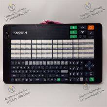
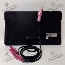
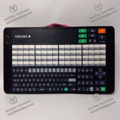
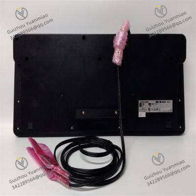
Material
Other, Global universal model
Condition
Other, Global universal model
Task
Other, Global universal model
Mathematical Model
Other, Global universal model
Signal
Other, Global universal model
Customized
Non-Customized
Structure
Other, Global universal model
Dimensions
96mm×96mm×100mm
Temperature
-10℃~+55℃
Control Accuracy
±0.1% FS
Yokogawa AIP830
I. Overview
The Yokogawa AIP830 is a high-performance intelligent temperature controller launched by Yokogawa Electric, belonging to the AIP series. It is specially designed for precise temperature regulation in industrial process control. Its core function is to achieve real-time monitoring and adjustment of temperature in heating/cooling systems through PID control algorithms, suitable for scenarios requiring strict temperature control such as chemical engineering, food processing, metallurgy, and heat treatment. The controller adopts a modular design, supports multiple input/output signals and communication protocols, and features high reliability and anti-interference capabilities, enabling stable operation in complex industrial environments.
II. Functional FeaturesHigh-Precision Control Capability
Temperature control accuracy reaches ±0.1℃ (typical value), with a sampling period as short as 50ms and fast response speed, suitable for processes sensitive to temperature fluctuations (e.g., semiconductor annealing, constant-temperature pharmaceutical reactions).
Flexible Input/Output Configuration
Supports multiple thermocouples (K, J, T, E, etc.), resistance thermometers (Pt100, Ni100, etc.), and analog inputs (e.g., 4-20mA, 0-10V). Output modes include relay contacts, SSR drive, and analog output (4-20mA), adapting to different actuators.
Advanced Control Algorithms
Built-in adaptive PID control algorithm automatically optimizes proportional (P), integral (I), and derivative (D) parameters to reduce overshoot and adjustment time; supports fuzzy control and ramp heating/cooling modes to meet complex process requirements.
Communication and Networking Capability
Standard RS-485 interface (Modbus RTU protocol), optional Ethernet interface (Modbus TCP), facilitating integration into DCS (Distributed Control System) or SCADA systems for remote monitoring and data logging.
Safety and Alarm Functions
Supports upper/lower temperature alarms and sensor fault alarms (e.g., open circuit, short circuit), and can send alarm signals via relay outputs or communication interfaces; features self-diagnosis to monitor hardware status in real time.
Human-Machine Interaction and Usability

III. Technical Parameters
| Parameter Type |
Specific Indicators |
| Input Signals |
Thermocouples: K, J, T, E, R, S, B, etc.; Resistance thermometers: Pt100 (3-wire/4-wire), Ni100; Analog: 4-20mA, 0-5V, 1-5V, etc. |
| Output Signals |
Relay contacts (250VAC/3A), SSR drive (DC 12V/50mA), analog output (4-20mA, 0-10V) |
| Control Accuracy |
±0.1% FS (full scale) or ±0.1℃ (whichever is larger), resolution 0.1℃ |
| Sampling Period |
50ms |
| Communication Interfaces |
Standard RS-485 (Modbus RTU), optional Ethernet (Modbus TCP) |
| Power Supply |
AC 100-240V (50/60Hz), power consumption ≤10VA |
| Operating Environment |
Temperature: -10℃~+55℃, humidity: 10%-90% (non-condensing) |
| Protection Class |
Front panel IP66 (dustproof and water jet-proof), back IP20 |
| Dimensions |
96mm×96mm×100mm (panel-mounted), compliant with DIN 43700 standard |
IV. Working Principle
The AIP830 achieves precise temperature control based on the closed-loop feedback control principle through the process of "signal acquisition - algorithm calculation - output adjustment - feedback correction," as follows:
Temperature Signal Acquisition
Thermocouples or resistance thermometers convert temperature into electrical signals, which are amplified and filtered by the signal conditioning circuit before being input into the controller. The controller converts analog quantities into digital quantities (A/D conversion).
Control Algorithm Calculation
The controller compares the collected temperature value with the setpoint (SP) and calculates the output value (MV) through the adaptive PID algorithm. When the temperature deviation is large, the algorithm automatically adjusts the proportional term for a fast response; as the deviation decreases, the integral term eliminates static errors; the derivative term suppresses overshoot. For nonlinear systems, fuzzy control can be enabled to optimize dynamic characteristics.
Output Adjustment Execution
Based on the calculation results, the controller drives heating/cooling equipment (e.g., heating wires, fans) through relays, SSRs, or analog outputs, adjusting power output (e.g., PWM pulse width modulation) to achieve temperature approaching the setpoint.
Closed-Loop Feedback Correction
Continuously acquiring temperature signals forms a closed-loop control, real-time correcting the output to ensure temperature stability within the target range. When system parameters change (e.g., load fluctuations), the adaptive algorithm automatically optimizes PID parameters to maintain control accuracy.

V. Common Faults and Solutions (Based on Similar Product Logic, Refer to the Official Manual for Details)▶ Signal Acquisition Faults
Fault Phenomenon: Display shows "OPEN" (sensor open circuit) or "SHORT" (short circuit).
Causes: Thermocouple/resistance thermometer cable breakage, loose terminal connections, or sensor damage.
Solutions: Check cable connections and replace damaged cables; measure sensor resistance with a multimeter to confirm damage and replace the sensor if necessary.
Fault Phenomenon: Abnormal temperature display (e.g., jumping, fixed value).
Causes: Signal electromagnetic interference, A/D conversion circuit failure.
Solutions: Add a shield layer to the cable and ground it; check the controller's grounding and replace the main board if necessary.
▶ Control Output Faults
▶ Communication Faults
▶ Hardware Faults
Fault Phenomenon: Controller has no display (black screen).
Causes: Blown power fuse, faulty power module, or loose display cable connection.
Solutions: Disconnect power, check if the fuse is blown (replace with the same specification); measure input power voltage; open the housing, re-plug the display cable, and replace the power board or display module if ineffective.
Fault Phenomenon: Internal abnormality alarm (e.g., "ERR" code).
Causes: Overheated internal circuit, lost memory parameters, or hardware failure.
Solutions: Check if the controller's cooling holes are blocked to ensure good ventilation; try power cycling and restoring factory settings; contact the manufacturer for maintenance or motherboard replacement.