

Home > Electrical & Electronics > Electrical Control System > Woodward 5448-906 REVSPM-D10 Digital Regulating Controller
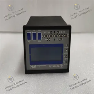
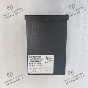
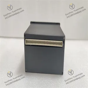
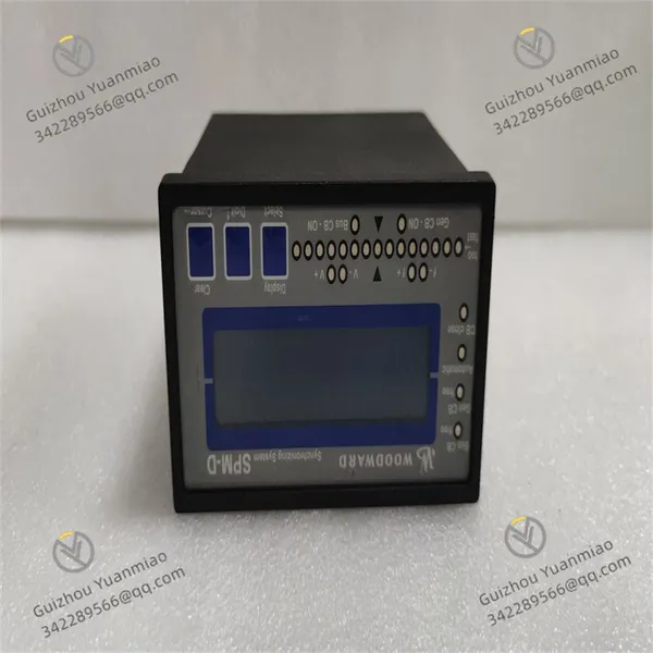
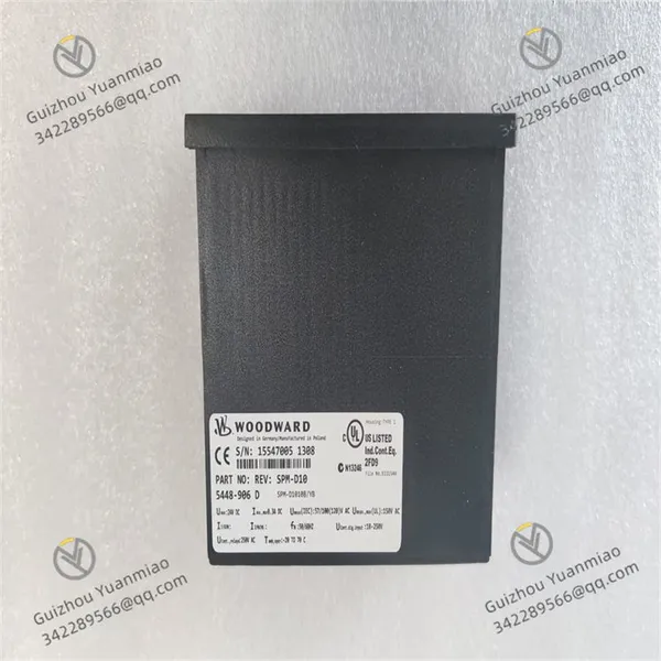
Woodward 5448-906 REVSPM-D10 Digital Regulating Controller

Negotiable
MOQ: 1 Piece (Price negotiable depending on order volume and customization)
Key Specifications
Get Latest Price
Material:
Other, Global universal model
Condition:
Other, Global universal model
Task:
Other, Global universal model
Payment & Shipping
Payment Methods:
Port of Shipment:
China
Delivery Detail:
Delivery time depends on order quantity.
Related Products
-
 Woodward 8237-1006 Electronic GovernorNegotiableMOQ: 1 Piece
 -
Woodward 8440-1546H Speed ControllerNegotiableMOQ: 1 Piece
-
Woodward 8440-1706 Speed ControllerNegotiableMOQ: 1 Piece
-
Woodward 8440-1713 D Speed ControllerNegotiableMOQ: 1 Piece
-
Woodward 9907-1290 Digital Speed ControllerNegotiableMOQ: 1 Piece
Material
Other, Global universal model
Condition
Other, Global universal model
Task
Other, Global universal model
Mathematical Model
Other, Global universal model
Signal
Other, Global universal model
Customized
Non-Customized
Structure
Other, Global universal model
Operating temperature
-40 ℃ to 70℃
Dimensions
Approximately 100mm×150mm×50mm
Weight
Approximately 0.8kg
Application ScopeSignal InputWorking Modes
Functional IntegrationOutput SignalDurabilityConfiguration and Protection

Send Inquiry to This Supplier

* Email
Want the best price?
Post an RFQ now!

Business Type
Trading Company
Year Established
2014
Factory Size
1,000-3,000 square meters
Product Certifications
SA8000
You May Also Like
-
Woodward 8200-1302 Digital GovernorNegotiableMOQ: 1 Piece
-
Woodward 9907-162 Digital GovernorNegotiableMOQ: 1 Piece
-
Woodward 9907-164 Digital GovernorNegotiableMOQ: 1 Piece
-
Woodward 9907-167 Digital GovernorNegotiableMOQ: 1 Piece
-
Woodward 9907-1183 Digital GovernorNegotiableMOQ: 1 Piece
-
Woodward 5466-258 Simplex Discrete Input/Output ModuleNegotiableMOQ: 1 Piece
-
Woodward 5466-316 Digital I/O ModuleNegotiableMOQ: 1 Piece
-
Woodward 5501-432 Actuator Control ModuleNegotiableMOQ: 1 Piece
-
Woodward 5501-467 Actuator Control ModuleNegotiableMOQ: 1 Piece
-
Woodward 5501-470 ControllerNegotiableMOQ: 1 Piece


