


Negotiable
MOQ: 1 Piece (Price negotiable depending on order volume and customization)
Key Specifications
Get Latest Price
Material:
Other, Global universal model
Condition:
Other, Global universal model
Task:
Other, Global universal model
Payment & Shipping
Payment Methods:
Port of Shipment:
China
Delivery Detail:
Delivery time depends on order quantity.
Related Products
-
 Woodward 9907-838 Load Sharing ModuleNegotiableMOQ: 1 Piece
 -
Woodward EGCP-2 8406-121 Generator ControllerNegotiableMOQ: 1 Piece
-
Woodward 5501-471 NetCon SIO Module 00:20NegotiableMOQ: 1 Piece
-
WOODWARD 3522-1004 ControllerNegotiableMOQ: 1 Piece
-
WOODWARD 8200-1300 Digital Speed Controller for Steam TurbineNegotiableMOQ: 1 Piece
Material
Other, Global universal model
Condition
Other, Global universal model
Task
Other, Global universal model
Mathematical Model
Other, Global universal model
Signal
Other, Global universal model
Customized
Non-Customized
Structure
Other, Global universal model
Operating Temperature
-22 to 158 °F (-30 to 70 °C)
Screen Size
8.4-inch LCD screen
Storage Temperature
-22 to 158 °F (-30 to 70 °C)
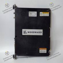
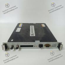
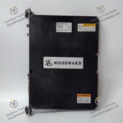
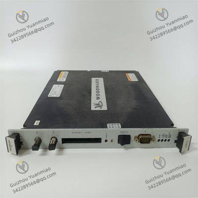
Woodward 5501-470Functional FeaturesTechnical SpecificationsApplication Scope

Send Inquiry to This Supplier

* Email
Want the best price?
Post an RFQ now!

1Yr
Business Type
Trading Company
Year Established
2014
Factory Size
1,000-3,000 square meters
Product Certifications
SA8000
You May Also Like
-
WOODWARD 8446-1019 Digital Speed Controller for Steam TurbineNegotiableMOQ: 1 Piece
-
WOODWARD 8290-191 Electrical Governor Control ModuleNegotiableMOQ: 1 Piece
-
Woodward 8444-1067 High Performance ModuleNegotiableMOQ: 1 Piece
-
WOODWARD 8440-1666 B Synchronizer ModuleNegotiableMOQ: 1 Unit
-
WOODWARD 5233-2089 High-Efficiency Control ModuleNegotiableMOQ: 1 Unit
-
WOODWARD 9907-1106 Current Pressure Converter CPC-IINegotiableMOQ: 1 Unit
-
WOODWARD 5466-425 Analog I/O ModuleNegotiableMOQ: 1 Unit
-
WOODWARD 5453-277 TMR Power Supply ChassisNegotiableMOQ: 1 Unit
-
WOODWARD 5501-381 TMR Power Supply UnitNegotiableMOQ: 1 Unit
-
WOODWARD 5453-279 MicroNet TMR ChassisNegotiableMOQ: 1 Unit


