








 Contact Platform Support
 Help Center
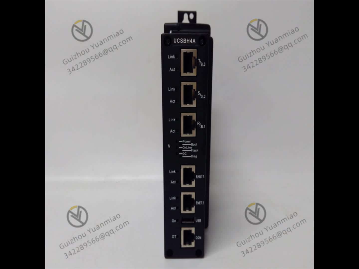
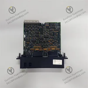
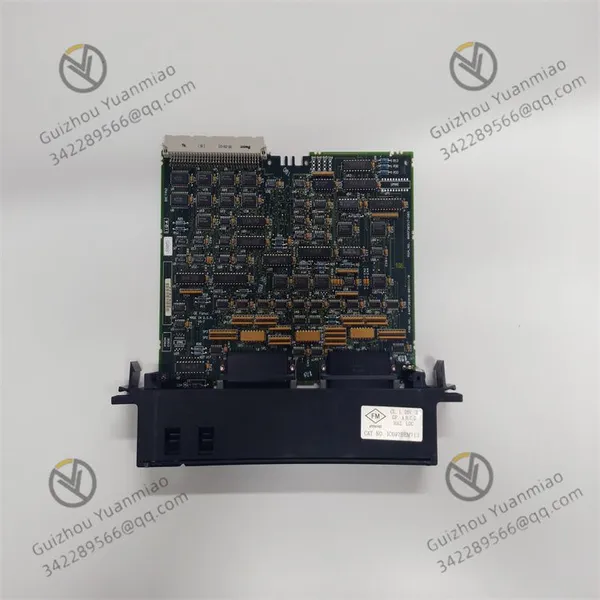
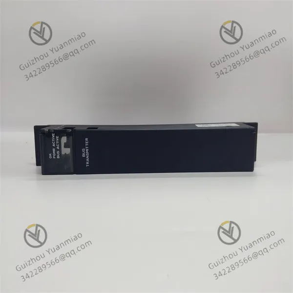
GE IC697BEM713 RX7i Series Bus Transmitter Module



Related Products
-
 GE IC697MDL653 Positive/negative Logic Discrete Input ModuleNegotiableMOQ: 1 Piece
 -
GE IC697CPX928-FE Central Processing Unit ModuleNegotiableMOQ: 1 Piece
-
GE IC697PWR748D High-performance Power ModuleNegotiableMOQ: 1 Piece
-
GE IC697CPM790 Communication Processor ModuleNegotiableMOQ: 1 Piece
-
Redundant Modules of GE IC698RMX016 RX7i SeriesNegotiableMOQ: 1 Piece
GE IC697BEM713 RX7i series bus transmitter module
Working principle
IC697BEM713, as the bus expansion core module of GE PacSystems RX7i series PLC, its working principle revolves around "bus signal transmission and expansion control". Through electrical signal conversion, data buffering and bus protocol management, it realizes high-speed data interaction between the main CPU rack and the expansion rack. The following is a detailed analysis from the core functional level:
I. Physical Layer and Electrical Characteristics of Bus Communication
Bus signal transmission mechanism
Electrical interface standard: It adopts the parallel bus electrical specification, is powered by a 5V DC power supply, supports differential signal transmission to reduce electromagnetic interference (EMI), and ensures the stable transmission of data on the extended bus.
Signal conversion logic: The module integrates a bus drive circuit internally to convert the TTL level signal sent by the CPU into a differential signal suitable for long-distance transmission. At the same time, it avoids signal reflection through impedance matching technology (such as terminal resistors) to ensure data integrity.
The principle of cable and distance limitation
The maximum cable length for the programming interface and expansion interface supported by the module is 50 feet (approximately 15.24 meters), which is due to:
When signals are transmitted in cables, they will be attenuated due to resistance and capacitance effects, and long-distance transmission may lead to level distortion.
The anti-interference capability of differential signals can maintain an effective signal-to-noise ratio (SNR) within 15 meters. Beyond this distance, additional relay equipment is required.
Ii. Data Transmission and Bus Protocol Management
Data transmission process
Master-slave communication architecture: IC697BEM713 serves as the "bus transmitter", acting as the "master device" in the main CPU rack, and the bus receiving module (such as IC697BEM711) connected through the expansion port acts as the "slave device", following the polling mechanism of "master transmission and slave reception" :
The CPU sends the data that needs to be transmitted to the expansion rack (such as I/O status, control instructions) to the BEM713;
The module encodes the data (such as adding check bits) and sends it to each slave module through the extended bus.
The data is received from the module and parsed, then forwarded to the I/O module of the corresponding expansion rack. At the same time, the feedback data of the expansion rack (such as input signals) is sent back to the BEM713, and then read by the CPU.
Data rate and buffering mechanism
The realization of a 500KB/s transmission rate: The module integrates a high-speed data buffer (such as a FIFO queue) internally, supporting the temporary storage and smooth transmission of burst data, and avoiding data loss caused by bus competition. For example:
When the CPU suddenly receives a large number of I/O refresh instructions, the buffer can temporarily store the data and send it frame by frame according to the bus protocol sequence to ensure the transmission efficiency.
Iii. Topology Construction and Address Mapping of Extended Racks
Electrical connection with Daisy chain topology
The module is connected to multiple bus receiving modules (up to 7) in a Daisy chain manner through the expansion port. Each receiving module corresponds to an expansion rack, forming "main rack → Expansion 1→ Expansion 2→..." Expand the cascade structure of "7". Its connection principle is:
Each BEM713 expansion port outputs a differential bus signal, which is connected to the input port of the next receiving module through a dedicated cable to form a closed bus loop.
Automatic mapping of I/O addresses
The module sets the address offset of the expansion rack through hardware dip coding or software configuration (such as Logic Developer), and the CPU automatically identifies the positions of the I/O modules of each expansion rack according to the address mapping table. For example:
The I/O address of the mainframe rack is 0-127. The address of the first expansion rack is automatically offset to 128-255, and so on, ensuring that the CPU can directly address all expansion modules.
Iv. Status Monitoring and Fault Tolerance Mechanism
Status feedback of LED indicator lights
OK lamp: Through the internal Power monitoring circuit and the Self-Test program (power-on self-test, POST), it detects in real time whether the module power supply and logic circuit are normal. If abnormal, it will go off or flash.
PGMR light: When a programmer (such as a handheld terminal or PC) communicates with the module through a parallel port, the indicator light flashes, reflecting the data transmission activity.
BUS light: Monitors the signal activity of the extended bus. It flashes when there is data transmission on the bus and can be used to determine whether the bus is blocked or interrupted.
Fault-tolerant handling of bus faults
The module is equipped with a built-in bus arbitration logic. When a bus conflict is detected (such as multiple devices sending data simultaneously), it automatically delays the sending and tries again. If the bus continues to fail (such as cable disconnection), an alarm will be triggered through the status light and an error code will be sent to the CPU, triggering a system redundant switch (if there is a redundant configuration).
V. Collaborative operation with the CPU and other modules
Interface protocol with the CPU
The module communicates directly with the CPU through the backplane of the mainframe rack and follows the internal bus protocol of the GE RX7i series (such as using specific address lines, data lines and control lines) to ensure clock synchronization and instruction parsing with the CPU. For example:
The CPU specifies the data transmission target (such as a certain I/O module of the expansion rack) through the address bus, and the BEM713 performs data forwarding after decoding the address.
Compatibility with I/O modules
Whether the expansion rack is connected to digital, analog or special function I/O modules, the IC697BEM713 is only responsible for the physical transmission of bus signals and does not interfere with the data content. The electrical characteristics of the I/O module (such as input voltage and output driving capability) are determined by itself, and the module transparently transmits data through the bus protocol.
Summary of Working Principle
The core function of IC697BEM713 is to build an "electrical signal bridge" in the PLC system. Through signal conversion at the physical layer, protocol management at the data link layer, and address mapping at the topology layer, it efficiently transmits control instructions from the main CPU to the expansion rack and returns on-site data. Its workflow can be summarized as: power supply → bus signal drive → data encoding and transmission → expansion rack addressing → status monitoring and feedback. It is suitable for medium and large-scale industrial control systems that require expansion of I/O points, such as production line expansion and centralized control of distributed equipment. In practical applications, attention should be paid to cable specification matching, rack address planning and bus terminal resistor configuration to ensure transmission stability.

Send Inquiry to This Supplier


You May Also Like
-
GE IC698CRE040 Ethernet Communication ModuleNegotiableMOQ: 1 Piece
-
GE IC698ETM001 Industrial Ethernet Switch ModuleNegotiableMOQ: 1 Piece
-
GE DS200TCTGG1A Printed Circuit BoardNegotiableMOQ: 1 Pair
-
GE DS200ADGIH1AAA Gas Turbine Control Circuit BoardNegotiableMOQ: 1 Piece
-
GE DS200TCTGG1A Turbine Tripping Circuit BoardNegotiableMOQ: 1 Piece
-
GE IS215ACLEH1B Application Control Layer ModuleNegotiableMOQ: 1 Piece
-
GE IS215UCVEH2A Industrial Automation ModuleNegotiableMOQ: 1 Piece
-
GE IS200MVRCH1ABA Analog Input/output BoardNegotiableMOQ: 1 Piece
-
GE IS200MVRDH1AAB Signal Processing ModuleNegotiableMOQ: 1 Piece
-
GE IS215WECAH1A Turbine Control System ComponentsNegotiableMOQ: 1 Piece


