








 Contact Platform Support
 Help Center
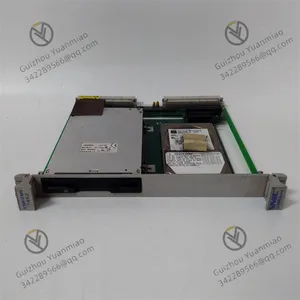
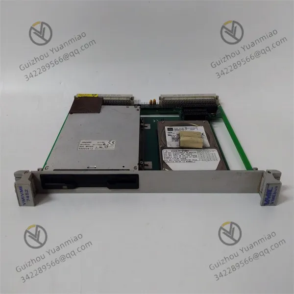
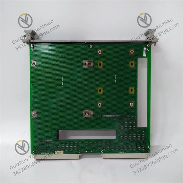
GE VMIVME-7452 Controller Module




Related Products
-
 GE VMIVME-7455 Single-slot Drive ModuleNegotiableMOQ: 1 Piece
 -
GE IC697CMM742 Ethernet Interface ModuleNegotiableMOQ: 1 Piece
-
GE IC697BEM713 RX7i Series Bus Transmitter ModuleNegotiableMOQ: 1 Piece
-
GE IC697MDL653 Positive/negative Logic Discrete Input ModuleNegotiableMOQ: 1 Piece
-
GE IC697CPX928-FE Central Processing Unit ModuleNegotiableMOQ: 1 Piece
GE VMIVME-7452 controller module
Faults and Responses
I. Power Supply and Power Supply Faults
1. The module cannot be powered on/the indicator light is not on
Possible reasons
The power adapter is faulty or the input voltage is abnormal (with a fluctuation range exceeding ±5%).
Poor contact of the VME bus slot, or loose or short-circuited power cables.
The power management chip inside the module burned out (such as overvoltage impact).
Solution
Use a multimeter to test the input voltage (3.3V/5.0V), confirm that the output of the voltage stabilizer or UPS is stable, and replace the faulty power adapter.
Reinsert and unplug the module, clean the oxide in the slot, and ensure that the pins are in close contact with the slot. Check whether the cable joints are oxidized or damaged. Replace the cables if necessary.
If the internal chip is damaged, it is necessary to contact the manufacturer for factory repair or module replacement.
2. Abnormal power indicator light (flashing/constantly on)
Possible reasons
The input ripple of the power supply is too large and is affected by electromagnetic interference.
The module is in an overloaded state (such as excessive power consumption of the expansion device).
Solution
Parallel filter capacitors at the power input end (refer to the specifications in the manual), or install modules away from strong electromagnetic sources (such as motors and transformers).
Check the power consumption of the extended equipment, disconnect unnecessary peripherals, and confirm whether the abnormality is caused by excessive load.
Ii. Communication and Interface Failures
The VME bus communication was interrupted
Possible reasons
Bus address conflict (multiple module address duplication).
The bus driver chip is faulty, or the slot signal transmission line is damaged.
Solution
Modify the module address through the configuration tool to ensure that the address within the VME bus is unique.
Use an oscilloscope to detect the bus signal waveform. If the driver chip is abnormal, it needs to be replaced with a chip of the same model (it is recommended to be operated by a professional).
2. Abnormal input/output (I/O) signals
Possible reasons
The 50-pin PCB wiring is incorrect (such as reversing the DI/DO channels), or the cable contact is poor.
External device signals exceed the compatibility range of the module (such as excessively high analog signal voltage), causing the interface chip to burn out.
Solution
Recheck the wiring against the manual to ensure that the DI/DO/AI/AO channels are correctly connected to the peripheral devices and reinforce the cable joints.
Measure the amplitude of the external signal with a multimeter. If it exceeds the rated input range of the module (such as the upper limit of the analog input voltage of 10V), a signal conditioning circuit (such as a voltage divider resistor) needs to be added.
Iii. Faults in storage and data processing
1. Hard disk/flash drive read/write failure
Possible reasons
Physical damage to storage media (such as bad sectors on hard disks and aging of flash memory chips).
The sudden read and write rates exceeded the specifications (flash memory write 4.0MB/s, read 6.0MB/s), resulting in data packet loss.
Solution
Scan the storage medium through the module management software. If bad sectors or incorrect counts are found, replace the floppy disk, hard disk or flash drive.
Optimize the data transmission protocol to avoid high-frequency burst reading and writing (such as batch transmission of large files), or add a caching mechanism.
2. Data processing delays or calculation errors
Possible reasons
The processor load is too high (such as the complex setting of multi-axis control parameters), resulting in operation timeout.
There are logical loopholes in the software program, or the driver version is incompatible with the module.
Solution
Reduce the number of synchronous axes in multi-axis control, or optimize control parameters (such as lowering the acceleration threshold) to reduce the load on the processor.
Upgrade to the latest official driver, re-debug the program logic, and eliminate dead loops or memory leak issues.
Iv.Abnormal control functions
1. Inaccurate multi-axis motion control
Possible reasons
The position/speed parameters are set beyond the mechanical limit (such as the maximum speed of the motor).
Interference from the encoder feedback signal leads to closed-loop control deviation.
Solution
Recalibrate the mechanical system to confirm that the module parameters (such as pulse equivalent and reduction ratio) match the actual mechanical structure.
Wrap a shielding net around the outer layer of the encoder cable to ensure reliable grounding at the grounding end and reduce electromagnetic interference.
2. The digital output (DO) is unresponsive
Possible reasons
The output port is disabled by software, or the output current exceeds the rated value (such as the maximum driving current of the port being 50mA), triggering overload protection.
The external load short-circuited, causing the port fuse to blow.
Solution
Check the DO port configuration through programming tools and enable the output function; Reduce the load current (such as by replacing the load with a high-resistance value).
Replace the fuse inside the module (if it is designed to be replaceable), or check if the peripheral devices are short-circuited. After repair, power on again.
V. Environmental and Hardware Wear Faults
1. Module overheating (temperature exceeding 50℃)
Possible reasons
The working environment temperature exceeds the specification (5℃ to 50℃), or the heat dissipation holes are clogged with dust.
Long-term full-load operation leads to excessive power consumption.
Solution
Add a forced cooling fan, clean the dust on the module surface and slots (once every three months), and ensure good ventilation.
Optimize task scheduling, avoid continuous high-load operation, and switch to sleep mode when idle to reduce power consumption.
2. Physical hardware damage (such as slot deformation, component detachment)
Possible reasons
Improper force during installation can cause the slot pins to bend, or the solder joints of components to loosen in a vibrating environment.
Static electricity punctured the chip (if operating without wearing an anti-static wristband).
Solution
Carefully correct the bent pins with a special tool. If it cannot be repaired, replace the VME slot. Re-weld the de-soldered components (professional welding equipment is required).
Before operation, wear an anti-static wristband and ground it to avoid touching the module circuit with bare hands in a dry environment.
Vi. Suggestions for Troubleshooting Process
Preliminary inspection: First, confirm whether the basic conditions such as power supply, wiring, and ambient temperature are normal, and observe the status of the module's LED indicator lights (such as power light, communication light, and error light).
Software diagnosis: Use the official debugging tool to read the error log, locate the specific fault code (for example, "E001" indicates communication timeout), and refer to the manual for the solution.
Hardware isolation: Gradually disconnect the expansion device and confirm whether the module anomaly is caused by peripheral device failure. Replace the suspected faulty cables, power supplies or storage media and conduct cross-tests.
Professional support: If self-troubleshooting proves ineffective, contact the technical support of GE manufacturer, providing the module serial number, fault phenomenon and debugging log. If necessary, return to the factory for inspection and repair.
Summary
The faults of VMIVME-7452 are mostly related to installation specifications, power supply stability, environmental interference and software compatibility. In daily maintenance, special attention should be paid to heat dissipation, anti-static and wiring reliability. When faults occur, follow the principle of "soft first, then hard; simple first, then complex" for troubleshooting to avoid blind disassembly that may cause secondary damage.

Send Inquiry to This Supplier


You May Also Like
-
GE IC697PWR748D High-performance Power ModuleNegotiableMOQ: 1 Piece
-
GE IC697CPM790 Communication Processor ModuleNegotiableMOQ: 1 Piece
-
Redundant Modules of GE IC698RMX016 RX7i SeriesNegotiableMOQ: 1 Piece
-
GE IC698CRE040 Ethernet Communication ModuleNegotiableMOQ: 1 Piece
-
GE IC698ETM001 Industrial Ethernet Switch ModuleNegotiableMOQ: 1 Piece
-
GE DS200TCTGG1A Printed Circuit BoardNegotiableMOQ: 1 Pair
-
GE DS200ADGIH1AAA Gas Turbine Control Circuit BoardNegotiableMOQ: 1 Piece
-
GE DS200TCTGG1A Turbine Tripping Circuit BoardNegotiableMOQ: 1 Piece
-
GE IS215ACLEH1B Application Control Layer ModuleNegotiableMOQ: 1 Piece
-
GE IS215UCVEH2A Industrial Automation ModuleNegotiableMOQ: 1 Piece


