


Related Products
-
 ICS Triplex 9300 9832 9802 Analog Input ModuleUS$ 200 - 1100MOQ: 1 Unit
 -
ICS Triplex T8110B Trusted TMR ProcessorUS$ 560 - 1700MOQ: 1 Unit
-
ICS Triplex T8461 Digital Output ModuleUS$ 460 - 1680MOQ: 1 Unit
-
Triconex 3503E Digital Output ModuleUS$ 800 - 1800MOQ: 1 Unit
-
Triconex 3604E Digital Output ModuleUS$ 500 - 1740MOQ: 1 Unit
Features Powerful Analog Input Function: It can achieve precise collection of various analog signals, such as voltage, current, temperature, pressure and other signals. It has high-precision analog-to-digital conversion capability, which can accurately convert the input analog signals into digital signals for the system to process and analyze. High-reliability Design: Adopting a Triple Module Redundancy (TMR) architecture, there are three independent processing channels inside, and each channel processes and compares the input signals simultaneously. This design can effectively improve the fault tolerance of the system. Even if one channel fails, the other two channels can still ensure the normal operation of the module, ensuring the stability and reliability of the system under various complex working conditions. Wide-range Input Adaptability: It supports a variety of input signal ranges and can be flexibly configured according to actual application requirements, making it suitable for the signal access of different sensors and measurement devices. For example, it can be adapted to pressure sensors and temperature sensors with different ranges. Comprehensive Diagnostic Function: It has a built-in self-diagnostic function, which can monitor the running status of the module in real time, detect various fault situations such as channel failures, communication anomalies, power problems, etc., and promptly feedback to users through indicator lights or communication interfaces, making it convenient for troubleshooting and maintenance. Rich Communication Interfaces: It is usually equipped with a variety of communication interfaces, such as Ethernet, serial ports, etc., and supports standard industrial communication protocols, such as Modbus, Profibus, etc., making it easy to carry out data interaction and integration with other devices (such as PLCs, DCS systems, upper computers, etc.), and realizing centralized monitoring and management of the system. Hot-swappable Function: It allows the module to be safely inserted or removed during the operation of the system without affecting the normal operation of the system. This feature greatly improves the maintainability and availability of the system and reduces the downtime.
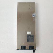
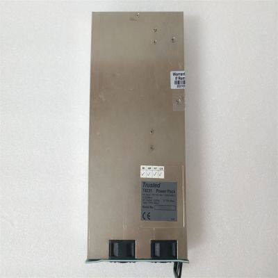
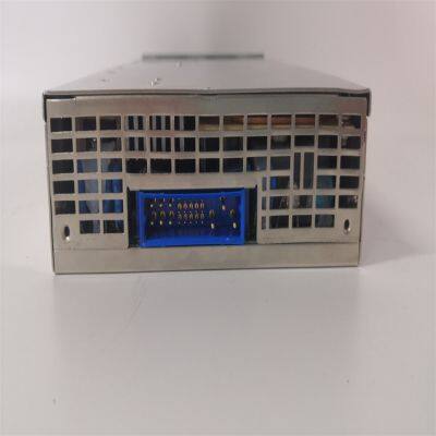
Installation Steps 1. Preparation before Installation Confirm that the module and its accessories are intact, including the module itself, the instruction manual, connection cables, etc. Prepare installation tools, such as screwdrivers, wrenches, etc. Select a suitable installation location to ensure that the installation environment meets the working requirements of the module, such as restrictions on temperature, humidity, electromagnetic interference, etc. At the same time, ensure that there is enough space at the installation location for easy operation and maintenance. Cut off the relevant power supply to ensure personal safety and equipment safety during the installation process. 2. Module Installation Install the T8231 module into the designated chassis or rack. According to the installation instructions of the chassis, use fixing devices such as screws or buckles to firmly fix the module in the installation position, and ensure that the module is closely connected to the chassis slot. Connect various cables, including power cables, analog input signal cables, communication cables, etc. When connecting, carefully check the interface types and pin definitions of the cables to ensure correct connections, and tighten the connectors to prevent loosening. At the same time, pay attention to the reasonable routing of the cables to avoid interference with other devices or cables. Carry out grounding connection, connect the grounding terminal of the module to a reliable grounding wire to ensure a good grounding effect, so as to improve the anti-interference ability and safety of the module. 3. Inspection after Installation Check again whether the installation of the module is firm and whether the cable connections are correct and not loose. Turn on the power supply, check whether the power indicator light on the module is normally on, and confirm that the module has been powered on normally. At the same time, observe the status of other indicator lights to determine whether the module is in a normal initialization state. Use relevant configuration software or tools to check whether the communication between the module and other devices is normal, and ensure that the module can correctly send and receive data.
Configuration Method 1. Preparation before Configuration Install the configuration software compatible with the T8231 module on the computer, and ensure that the software version matches the module. Connect the computer to the module using a communication cable, and ensure that the communication connection is normal. You can verify the success of the connection through the communication test function of the software. 2. Configuration Process Launch the configuration software, and search for and identify the connected T8231 module. Set the analog input parameters. According to the type of the actually connected sensor and the signal range, configure the parameters such as the range, resolution, and filtering method of the input channel. For example, if a 4-20mA current signal is connected, set the corresponding range and signal type. Configure the communication parameters, including the communication protocol, baud rate, IP address, etc., so that the module can communicate effectively with other devices. Ensure that the communication parameters are consistent with those of the connected devices (such as PLCs, upper computers, etc.). Carry out the diagnostic settings of the module, and enable or adjust the diagnostic function parameters of the module as needed, such as the fault alarm threshold, diagnostic cycle, etc. Save the configuration parameters and download the configuration to the module, so that the module runs according to the set parameters. 3. Testing after Configuration Apply a known standard signal to the analog input channel of the module, check whether the module can correctly collect and convert the signal, and check whether the collected data is accurate through the configuration software. Simulate some fault situations, such as disconnecting the input signal cable, simulating a channel failure, etc., and check whether the diagnostic function of the module works properly and whether it can send alarm information in a timely manner. Conduct a communication test. Through data interaction with other devices, verify whether the communication function of the module is normal and whether the data transmission is stable and accurate.
Main Products:
Covering world-renowned brands:
Bently Nevada、Triconex、Woodward、Foxboro、Westinghouse、Reliance、Schneider Modicon、ABB、Allen-Bradley、Motorola、GE Fanuc、Yaskawa、ACSO、YOKOGAWA、Rexroth、NI、Bosch Rexroth、ICS Triplex、Kollmorgen、Mitsubishi、MOOG、Emerson、B&R、SST、ALSTOM、EPRO、HIMA、HONEYWELL、prosoft、AMAT 、SIEMENS、KUKA、LAM
Product categories include: DCS system parts, robot system spare parts, large-scale servo system components, widely applied in power, chemical, metallurgy, smart manufacturing, and other industries.
Service Advantages:
✅ Original imports with quality assurance
✅ Ample stock for rapid delivery
✅ Professional team for technical support
✅ Global logistics for worry-free coverage

Send Inquiry to This Supplier


You May Also Like
-
Triconex 4119A Enhanced Intelligent ModuleUS$ 420 - 1860MOQ: 1 Unit
-
Triconex 8112 Remote Expansion ChassisUS$ 400 - 2100MOQ: 1 Unit
-
Woodward 2301A 9907-018 Low-Voltage Load Sharing and Speed Control DeviceUS$ 200 - 1600MOQ: 1 Unit
-
WOODWARD 5466-316 Analog Combo ModuleUS$ 300 - 1500MOQ: 1 Unit
-
WOODWARD 8440-1713 D Servo Drive ModuleUS$ 300 - 1400MOQ: 1 Unit
-
Woodward 8200-1302 Digital Governor Turbine ControlUS$ 400 - 1800MOQ: 1 Unit
-
Woodward 9907-164 Digital Microprocessor Controller ModuleUS$ 450 - 1850MOQ: 1 Unit
-
Woodward 9907-838 Load Sharing ModuleUS$ 380 - 1540MOQ: 1 Unit
-
Honeywell CC-PCNT02 51454551-275 Controller ModuleUS$ 200 - 1000MOQ: 1 Unit
-
Honeywell FC-RUSIO-3224 Universal I/O ModuleUS$ 300 - 1600MOQ: 1 Unit


