

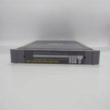
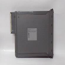
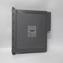
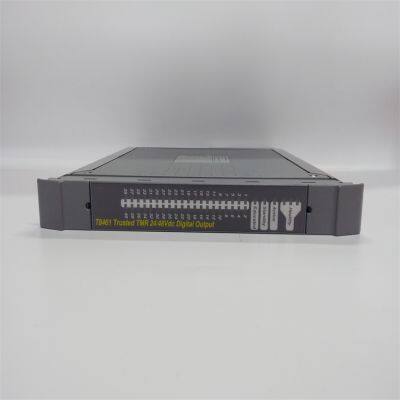
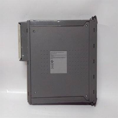
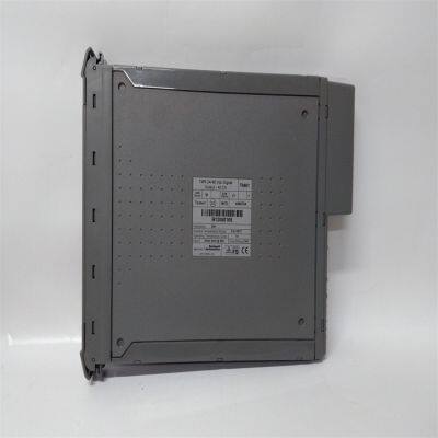
ICS Triplex T8461 Digital Output Module
Related Products
-
 ICS Triplex T8231 Power Pack 24 VdcUS$ 640 - 1750MOQ: 1 Unit
 -
ICS Triplex 9300 9832 9802 Analog Input ModuleUS$ 200 - 1100MOQ: 1 Unit
-
ICS Triplex T8110B Trusted TMR ProcessorUS$ 560 - 1700MOQ: 1 Unit
-
Triconex 3503E Digital Output ModuleUS$ 800 - 1800MOQ: 1 Unit
-
Triconex 3604E Digital Output ModuleUS$ 500 - 1740MOQ: 1 Unit
Features Output Capacity: It can be connected to up to 40 field devices. Each module has 40 Triple Module Redundancy (TMR) output points and is equipped with 8 independent power supply groups, with each group having 5 output channels. This can meet the power requirements of different devices. Diagnosis and Protection: It has comprehensive and automatic diagnosis and self-checking functions. Each channel has automatic line monitoring, which can detect open circuits, short circuits in field wiring, and load faults. It has a photoelectric isolation barrier capable of withstanding a 2500V pulse, and automatic overcurrent protection (for each channel), eliminating the need for external fuses. Event Reporting: It supports on-board Sequence of Events (SOE) reporting with a resolution of 1ms, which helps to quickly locate problems. Hot Replacement: Online hot replacement can be configured using a dedicated Companion (adjacent) slot or SmartSlot (one spare slot for multiple modules), improving the system's availability.
Installation Steps Preparation Work: Before starting the installation, it is necessary to check that the RSLinx® gateway has been installed and configured, the ControlFLASH file has been downloaded from the Rockwell Automation website and installed in the ControlFLASH program, the IP address has been configured for the processor module, and the T8461C processor module has been restarted in recovery mode. Module Installation: Install the T8461 module into the corresponding chassis. According to the installation instructions of the chassis, use fixing devices such as screws or buckles to secure the module in the installation position. Connect various cables, including power cables and signal cables, etc. Pay attention to the types of cable interfaces and pin definitions to ensure correct connections, and tighten the connectors to prevent loosening. Installation Inspection: Check whether the connection between the module and the chassis is firm and whether the cable connections are correct. After turning on the power supply, check whether the power indicator light of the module is normally on, check whether the module can start normally and perform a self-check, and at the same time, confirm whether the output status indicator lights and module status indicator lights on the front panel are showing normally.
Configuration Method It usually needs to be configured through dedicated configuration software. The general steps are as follows: Connection and Identification: Connect the computer to the module using a communication cable to ensure normal communication. Launch the configuration software, and search for and identify the connected T8461 module. Parameter Setting: Set relevant parameters according to actual needs, such as the type, amplitude, frequency, etc. of the output signal, as well as relevant parameters of the diagnosis function and line monitoring function. For example, the line monitoring function of each channel can be configured, including selecting whether to enable it and setting relevant thresholds; configure diagnostic parameters, such as the trigger conditions for fault reports, etc. Function Testing: After completing the configuration, conduct a function test to check whether the module can correctly output signals according to the configuration requirements, and whether the diagnosis and protection functions are working properly. For example, simulate some fault situations to see if the module can detect them in a timely manner and generate corresponding diagnostic information.
Troubleshooting Methods
1. Hardware Connection Inspection: Check the power connection to ensure that the power cable is firmly connected. Use a multimeter to measure whether the power supply voltage is within the rated range of 20 to 32 volts DC. Confirm that the module is correctly installed, closely connected to the chassis slot, and the fixing screws are tightened. Check all connected cables, including output control cables, communication cables, etc., to ensure that the connectors are firm, without signs of looseness, oxidation, or damage, and replace the cables if necessary.
2. Indicator Light Status Analysis: If the power indicator light is not on or flashes abnormally, check the power supply and the internal power circuit of the module. The output status indicator lights can help determine the output status of each channel and whether there are field wiring faults. If the indicator light of a certain channel shows abnormally, there may be a problem with that channel. The module status indicator lights can indicate the health status and operating mode of the module. Refer to the module manual to understand the specific meaning and determine whether the module is operating normally.
3. Output Signal Inspection: Check whether the load is working properly and whether its rated voltage, current, and other parameters match the output capacity of the module. Send test signals to the output channels of the module through software or testing tools to check whether the module can output correctly. If a certain output channel does not work properly, it may be that the hardware circuit of this channel has a fault, such as damage to the output drive circuit, failure of the interface chip, etc. You can try to replace the output channel (if there is a redundant channel) to confirm the problem.
4. Communication Fault Troubleshooting: Confirm whether the communication parameter settings of the module, such as the communication protocol, baud rate, data bits, stop bits, parity check, etc., are correct, and whether the communication parameters of other devices communicating with the module are consistent. Check whether the communication cable is normal and whether the network connection is normal. For Ethernet communication, you can use the ping command to test the network connectivity between the module and other devices. If the communication cable and parameter settings are normal, it may be that the communication interface of the module has a fault. Try to replace the communication interface (if there is a redundant interface) or use other communication methods to confirm.

Send Inquiry to This Supplier


You May Also Like
-
Triconex 4119A Enhanced Intelligent ModuleUS$ 420 - 1860MOQ: 1 Unit
-
Triconex 8112 Remote Expansion ChassisUS$ 400 - 2100MOQ: 1 Unit
-
Woodward 2301A 9907-018 Low-Voltage Load Sharing and Speed Control DeviceUS$ 200 - 1600MOQ: 1 Unit
-
WOODWARD 5466-316 Analog Combo ModuleUS$ 300 - 1500MOQ: 1 Unit
-
WOODWARD 8440-1713 D Servo Drive ModuleUS$ 300 - 1400MOQ: 1 Unit
-
Woodward 8200-1302 Digital Governor Turbine ControlUS$ 400 - 1800MOQ: 1 Unit
-
Woodward 9907-164 Digital Microprocessor Controller ModuleUS$ 450 - 1850MOQ: 1 Unit
-
Woodward 9907-838 Load Sharing ModuleUS$ 380 - 1540MOQ: 1 Unit
-
Honeywell CC-PCNT02 51454551-275 Controller ModuleUS$ 200 - 1000MOQ: 1 Unit
-
Honeywell FC-RUSIO-3224 Universal I/O ModuleUS$ 300 - 1600MOQ: 1 Unit


