

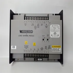
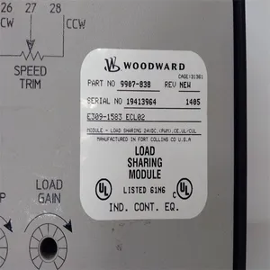
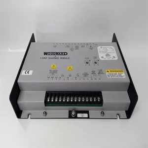
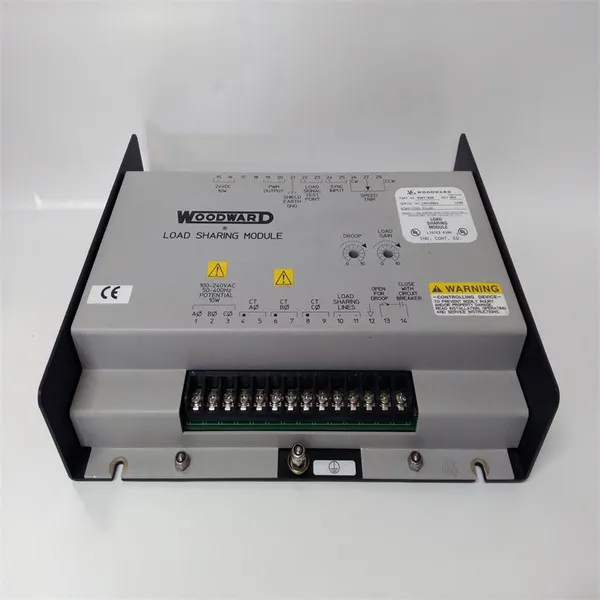
Woodward 9907-838 Load Sharing Module


Related Products
-
 Woodward 2301A 9907-018 Low-Voltage Load Sharing and Speed Control DeviceUS$ 200 - 1600MOQ: 1 Unit
 -
WOODWARD 5466-316 Analog Combo ModuleUS$ 300 - 1500MOQ: 1 Unit
-
WOODWARD 8440-1713 D Servo Drive ModuleUS$ 300 - 1400MOQ: 1 Unit
-
Woodward 8200-1302 Digital Governor Turbine ControlUS$ 400 - 1800MOQ: 1 Unit
-
Woodward 9907-164 Digital Microprocessor Controller ModuleUS$ 450 - 1850MOQ: 1 Unit
The Woodward 9907 - 838 is a Load Sharing Module (LSM) of Woodward Inc., mainly used for the isochronous and droop load sharing control of engines in generator set applications. The following are its features and advantages: Powerful Load Sharing Function: It can achieve load sharing between engines of Woodward equipment and non-Woodward equipment. It is suitable for engines equipped with different types of speed control inputs, including engines with ±3 VDC speed setting inputs, 0.5 to 4.5 VDC inputs, or PWM inputs. It has isochronous and droop load sharing functions. Isochronous load sharing can adjust the load when two or more generators are operating in parallel; droop load sharing can reduce the output under no-load and full-load conditions. Easy to Set up and Operate: This module is easy to set up, which reduces the difficulty of installation and debugging and saves time and labor costs. The front panel has a simple design. Function keys such as the emergency trip key and the backspace/delete key are reasonably arranged. There are also a navigation cross key, soft key commands, and four LEDs for associated control and hardware status, which facilitate operators to carry out various operations and monitoring. Good Communication and Compatibility: The sync input is compatible with the Woodward SPM - A synchronizer, making it easy to work in coordination with other related devices. It can be connected to a variety of Woodward power generation accessories. Equipped with RS - 232/RS - 422 slots and the Modbus protocol, it is convenient for data exchange and remote monitoring with other control systems. Strong Environmental Adaptability: The operating temperature range is from - 40°C to 70°C (-40°F to 158°F), which can adapt to various industrial environment temperature conditions. It can withstand an impact of up to 40g and a sawtooth pulse of 11 milliseconds, having good shock resistance performance and being able to work stably in an industrial environment with vibrations. Excellent Electrical Characteristics: The input voltage range is 18 - 32 VDC, which is suitable for a variety of DC power supplies. The 3-phase PT input is 95 - 130 VAC, which can meet the input requirements of different power systems. The output is a + 0.5 - +4.5 VDC analog signal, which can precisely control parameters such as speed.
General Installation and Debugging Steps of the Woodward 9907 - 838 (Load Sharing Module): Installation Steps:
1. Preparation Work: Ensure that you have understood the installation requirements and safety precautions of the equipment, and prepare the required installation tools, such as screwdrivers, wrenches, etc. Check whether the appearance of the module is damaged and whether the accessories are complete.
2. Select the Installation Location: Select a dry, well-ventilated place without severe vibrations to install the module. It is usually recommended to install it in a control cabinet to provide appropriate protection. Ensure that there is enough space at the installation location for convenient wiring and subsequent maintenance operations.
3. Fix the Module: Use appropriate screws to fix the module at the selected location, ensuring that the module is firmly installed and will not loosen.
4. Power Connection: According to the power requirements of the module, connect an 18 - 32 VDC DC power supply. Pay attention to correctly connecting the positive and negative poles of the power supply to avoid damage to the module caused by reverse connection.
5. Signal Input Connection: For the 3-phase PT input (95 - 130 VAC), connect the corresponding voltage signal wires according to the correct phase sequence. Ensure that the connection is firm to avoid poor contact. Connect the speed setting input wires. According to the type and requirements of the engine, connect the ±3 VDC speed setting input, 0.5 to 4.5 VDC input, or PWM input wires. If it is necessary to connect the sync input (compatible with the Woodward SPM - A synchronizer), make the connection according to the corresponding interface requirements.
6. Output Connection: Connect the + 0.5 - +4.5 VDC analog signal output wire and connect it to the equipment or system that needs to be controlled, such as the speed control unit of the engine. If there are other output signals (such as relay outputs, etc.), make the connection according to specific application requirements.
7. Communication Connection (Optional): If it is necessary to achieve remote monitoring or data exchange with other control systems, use the RS - 232/RS - 422 slots and the Modbus protocol for communication connection. Connect the corresponding communication cables and ensure that the communication parameter settings are correct.
Debugging Steps:
1. Check the Wiring: Before powering on, carefully check whether all the wiring is correct to ensure that there are no short circuits, open circuits, or wrong connections. Power-on Test: Turn on the power of the module and observe whether the indicator lights on the module light up normally. If there are abnormal indicator lights on, troubleshoot the faults according to the fault code table of the module (usually in the product manual).
2. Basic Parameter Setting: Use the function keys and the display screen on the front panel to enter the setting menu of the module. Set basic parameters, such as the working mode (isochronous or droop load sharing), speed setting value, load distribution ratio, etc. Make reasonable settings according to the actual application requirements.
3. Load Sharing Test: Start the generator set and make multiple engines operate in parallel. Observe whether the module can achieve the expected load sharing function and check whether the load distribution of each engine is uniform. If the load distribution is not uniform, adjust the relevant parameters of the module, such as the droop coefficient, etc.
4. Communication Test (if communication has been connected): Use the corresponding communication software or tools to test whether the communication between the module and other devices or systems is normal. Send and receive data and check the accuracy and integrity of the data.
5. Function Verification: Simulate various working scenarios, such as increasing or decreasing the load, starting or stopping the engine, etc., to verify whether the various functions of the module work normally. Check whether the alarm and protection functions of the module are normal. For example, when an abnormal situation occurs, whether the module can promptly issue an alarm and take corresponding protective measures.
6. Record and Save: Record the parameters set and the test results during the debugging process for subsequent reference and maintenance. If necessary, the set parameters can be saved in the memory of the module or backed up to an external storage device.

Send Inquiry to This Supplier


You May Also Like
-
Honeywell CC-PCNT02 51454551-275 Controller ModuleUS$ 200 - 1000MOQ: 1 Unit
-
Honeywell FC-RUSIO-3224 Universal I/O ModuleUS$ 300 - 1600MOQ: 1 Unit
-
Honeywell FC-SAI-1620M Safety Manager System ModuleUS$ 200 - 1500MOQ: 1 Unit
-
Kollmorgen S20330-SRS Digital AC Servo DriverUS$ 200 - 1800MOQ: 1 Unit
-
ALSTOM N897093511D N897093051D DIAGNOSTICA N897093400H Diagnostic ModuleUS$ 300 - 1500MOQ: 1 Unit
-
LAM 810-046015-010 Circuit BoardUS$ 350 - 1400MOQ: 1 Unit
-
National Instruments PXIE-8840QC Embedded ControllerUS$ 300 - 1600MOQ: 1 Unit
-
National Instruments PXI-4071 Digital MultimeterUS$ 400 - 1600MOQ: 1 Unit
-
National Instruments PXI-8423 Communication ModuleUS$ 360 - 1640MOQ: 1 Unit
-
Emerson WH5-2FF 1X00416H01 Power Supply ModuleUS$ 260 - 1570MOQ: 1 Unit


