Circuit Testing Insights & Buyer's Guide
In the rapidly changing domain of electronics, it is essential to ascertain the reliability and functionality of a circuit board. In-circuit testing (ICT) becomes a principal tool during testing, providing a rigorous examination of printed circuit boards (PCBs) and their discrete components. An ICT concentrates on the electrical parameters and actual functioning of the circuit for exact testing; hence, it is a very important tool in quality assurance. The article goes through the details of ICT and outlines its importance and utility in the arena of circuit testing.
Understanding In-Circuit Testing (ICT)
What is In-Circuit Testing?
In-circuit testing is electrical testing done so that probes can test every component on a printed circuit board. Test fixtures like a bed-of-nails, or flying probe, make reliable electrical contact with either test pads on the board or test pins potted into the board. It is very precise, verifying that electronic devices are found without faults so that every component works within its proper parameters. ICT covers virtually everything the PCB has to offer, from the measurement of voltage, capacitance, and other electrical parameters to ensuring the reliability and functionality of the circuit.
Advantages of ICT
ICT and its advantages make were of PCB testing an alternative. One of the most important benefits is the complete automation of the test process, which increases efficiency and minimizes human errors. ICT performs reliable tests to determine faults at the component level so issues can be remedied before they evolve into costly faults. Moreover, this method testing supports mass production-level testing on each PCB now, thereby assuring that only those are accepted into the market that boast well-tried quality. When ICT is incorporated into the testing system, the manufacturers can be sure of the precise and consistent evaluation of printed circuit board assemblies.
Typical Application Domain of ICT
The in-circuit testing finds its application across many industries due to its capacity for ensuring the quality and performance of electronic devices: consumer electronics, PCB testing, automotive systems, telecommunication equipment; industrial control systems, ICT takes into consideration the use of test systems that can accommodate test equipment, such as boundary scan testing, functional testing depending upon the particular requirements of the test. ICT ensures that the electronic devices comply with the required standard levels and can reliably perform in applications through thorough testing of key components on a PCB. The versatility of ICT has remained a major factor behind its broad adoption by various industries.
Types of In-Circuit Tests
Functional Testing vs. ICT
Functional testing and in-circuit testing (ICT) complement each other chaotically in the testing ecosystem for printed circuit boards. ICT inspects single components on the board, whereas functional testing checks PCB behavior as a whole. Testing the latter involves simulation under that kind of real-time condition wherein the PCB is supposed to work at actual environmental parameters. Combining these two methods can assure manufacturers that they have tested each single functionality and reliability of the component.
Boundary Scan Testing
Boundary scan testing is a very good complementary test method for traditional in-circuit tests to verify the integrity of the PCB non-invasively. It uses specific test points on the PCB, avoiding the need for physical probing to the point. It is especially useful for testing modern PCB designs, where high-density components limit test access. Boundary scan testing involves the use of test equipment and software to test the connections and functionality of components on a pin-by-pin level, giving it fine control over testing the digital signal paths. Boundary scan testing would integrate within the ICT system to empower the full automation of the testing process and ensure parity with quality and reliability assured standards.
Automated Test Equipment
The automated test equipment (ATE) created a big revolution in in-circuit testing, especially catering to large-scale production. ATE would typically automate the entire testing process, burglarizing the application of a variety of test fixtures and testers to perform the test on more than one PCB in parallelly. More importantly, this decreases human-related error, which is wrong to say if testing results are trustworthy. ATE supports other types of testing as well, which would include the in-circuit tests and functional testing, so that manufacturers can perform all-encompassing testing on different types of PCBs. By adopting ATE, companies ensure proper testing of their printed circuit board assemblies in terms of performance and reliability, and return provide a high-grade level of quality assurance in the manufacture of electronic devices.
Key Components of the ICT-A Process
Importance of Testing Fixtures
Testing fixtures form an integral part of the in-circuit test process, serving as the link between the PCB and the test system. These fixtures, which can be of various types such as the bed-of-nails or flying probes, achieve electrical contact with the test points on the PCB. With the testing fixture securing the board in place, designers achieve the accuracy needed to test individual components, such as resistors, capacitors, and integrated circuits, using the test probes. It is through the use of good testing fixtures that the in-circuit test process is made most reliable because such fixtures maintain consistent contact while minimizing the risk of damage to a PCB. These testing fixtures are therefore essential for complete testing and assessing the overall quality and functionality of an electronic device.
Types of Testers Used in ICT
Various types of testers are utilized in in-circuit testing, each set fulfilling certain peculiar testing demands and strengthening the testing procedure. A conventional bed of nails tester involves a grid supplied with spring-loaded test pins used to make contact with designated test pads on a PCB to detect open circuits and short circuits. Alternatively, flying probe testers take a more flexible approach, using movable probes to access test points without requiring the fabrication of expensive custom fixtures. This is most useful for testing at low volumes or in prototypes where design changes are frequent. By executing test automation with these modern testers, manufacturers guarantee reliability in their test outcomes and meet the highest quality assurance standards across varying PCB designs and production volumes.
PCB Design Considerations
PCB design is the very factor that constitutes the core of in-circuit testing, as it directly influences the accessibility and accuracy of testing in this process. Designers should carefully develop the positioning of test points so that they are intuitively accessible by test probes. The design of the board itself, such as components' spacing and routing of traces, should prevent any interference that might make electrical contacts unreliable during the test. Moreover, a designer should factor in the need for test pads and vias suitable for ICT fixtures, as this will assist in simplifying the testing process and improve fault detection capability. Given the nature of ICT, it is desirable for all considerations regarding PCB design to be made to ease precise testing, minimize test-related errors, and, above all, give the test process reliability and cost-effectiveness.
The ICT Testing Process
Step-by-Step Guide to ICT
The In-Circuit Test (ICT) process is highly systematic in ensuring that printed circuit boards (PCBs) undergo thorough testing. It starts with PCB preparation, wherein test points are set up electrically to be contacted by test probes. The PCB is then mounted on a test fixture, either bed-of-nails or flying probe, that serves as the go-between for the PCB and test equipment. The fixture maintains contact and alignment so that in-circuit testers can accurately measure electrical parameters, such as resistance and capacitance. Afterward, the tests are automated for the ICT equipment to verify components piece by piece and identify faults like open circuits, shorts, etc., through a well-guided testing procedure that ensures reliable test results, therefore guaranteeing the quality and functionality of the electronic devices.
Common Troubleshooting Techniques
In association with ICT, troubleshooting is very important in assuring the reliability of electronic devices. The regular troubleshooting techniques analyze test results to find any probable faults in the circuitry. Technicians mostly use boundary scan testing to diagnose faults without using physical probes; this method is useful, especially for densely populated PCBs. Functional testing is also used to simulate real-life conditions and check if the circuit fulfils its intended purpose. Oscilloscopes and multimeters form a part of the test equipment that find the voltage and other parameters that help diagnose short circuit, open circuit, etc. In such a manner, the amalgamation of these troubleshooting methods within the ICT procedure goes a long way to find and fix any faults so that good quality and performance of PCB assemblies are ensured.
Safety Considerations in Testing
Safety measures must be followed during ICT at every stage due to the nature of electrical testing and handling of sensitive electronic components. Safety measures must be taken to prevent any damage to the test equipment and PCBs. The test fixture provides stable electrical contact without putting undue pressure on the components during their use. The technicians must wear anti-static wristbands to prevent electrostatic discharge that may damage the circuitry. Proper grounding of the test system is essential to prevent electrical hazards. Moreover, personnel should be trained on the correct methods of handling test probes and relevant test equipment to reduce the risk of accidents. Attending to safety considerations during testing helps in protecting workers and products, and thus perpetuates a reliable and safe testing environment.
Frequently Asked Questions (FAQs)
What is circuit testing?
Circuit testing refers to the process of verifying the functionality and integrity of electronic circuits. This testing is crucial in ensuring that each component within a circuit operates as intended. Techniques such as continuity testing, functional testing, and boundary-scan testing are commonly employed. These methods help identify faults or defects in circuit designs, which can lead to improved reliability and performance. Circuit testing is especially important in industries like telecommunications, automotive, and consumer electronics. Effective circuit testing can save time and resources by catching issues early in the design phase.
Why is circuit testing important?
Circuit testing is essential for several reasons, primarily for ensuring the reliability and safety of electronic devices. By performing thorough testing, manufacturers can prevent potential failures that could lead to significant financial losses or safety hazards. Additionally, circuit testing helps maintain compliance with industry standards and regulations. It also facilitates improvements in product design by identifying areas that require enhancement. Ultimately, circuit testing contributes to customer satisfaction by ensuring that products meet performance expectations. The importance of circuit testing cannot be overstated in the fast-paced electronics market.
What are the different types of circuit testing methods?
There are several types of circuit testing methods, each suited for specific applications. Among the most common are functional testing, which assesses whether the circuit operates according to its specifications, and in-circuit testing, which checks the individual components of a circuit while it is assembled. Another method is boundary-scan testing, which allows for testing without physical access to the pins of the components. Other techniques include JTAG testing and automated test equipment (ATE) testing. These methods provide comprehensive coverage of potential issues, ensuring the circuit operates reliably under various conditions. Choosing the right testing method is critical for effective circuit verification.
How can I perform circuit testing at home?
Performing circuit testing at home can be achieved with some basic tools and an understanding of electronics. Start by gathering essential equipment such as a multimeter, which can measure voltage, current, and resistance. Begin with simple circuits to familiarize yourself with testing techniques like continuity testing, which checks for complete paths in the circuit. You can also use a breadboard for prototyping and testing designs without soldering. Online resources and tutorials can guide you through various testing methods and troubleshooting techniques. Safety is paramount, so always take precautions when working with electrical components.
What tools are used for circuit testing?
Several tools are essential for effective circuit testing, catering to different testing methods. A multimeter is one of the most versatile tools, allowing you to measure voltage, current, and resistance. Oscilloscopes are also crucial for visualizing electrical signals in circuits, providing insight into performance over time. For more advanced testing, automated test equipment (ATE) can streamline the testing process and improve accuracy. Additionally, logic analyzers help in diagnosing digital circuits by capturing and analyzing their signals. Each of these tools plays a vital role in ensuring that circuits function correctly and efficiently.


 Intelligent RM620 Precision Thermal Imager – Custom Spot/Area Temperature Measurement & 8× Zoom for HVAC & Electronic Circuit TestingNegotiableMOQ: 10 PiecesTransport Package: OtherSpecification: 258.4×105.1×102.3mmTrademark: RaythinkOrigin: YantaiRaythink Technology Co., Ltd.
 2 Yrs
2 Yrs MMLB01 Test Plug Relay Module/Test Multiple Circuits 5X00419G02US$ 3670.00MOQ: 1 PalletI/O Number: MMLB01Place of Origin: AmericaCommunication Interface: ModubusProduct name: Test plug relay module/Test multiple circuitsXiamen Xiongba E-commerce Co., LTD
 Intergrated Circuit Test, Precision Printed Circuit Board, Precision PcbaUS$ 0.1 - 11MOQ: 1 PiecePlace of Origin: Guangdong, ChinaBrand Name: MOKOModel Number: MK60523BCBase Material: FR4Shenzhen Moko Technology Ltd.
 2013 Hot Sale Www.golden-laser.org Electronic Component in Circuit TestingUS$ 1 - 3,600MOQ: 1 PieceCertification: CE, ISO13485, SFDA, PRC IMPORT & EXPORTPlace of Origin: Beijing, ChinaBrand Name: GLBeijing Goldenlaser Development Co., Ltd.
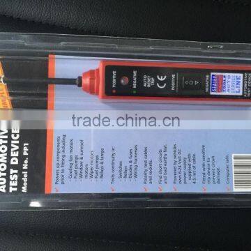 Auto Electrical Circuit Test Probe Device - 6-24 Volt DC - 4.5m Cable - SealeyNegotiableMOQ: 500 PiecesPlace of Origin: Zhejiang, ChinaModel Number: MT-4.5Power: ElectronicUsage: Auto Testing MachineYongkang MASTER Hardware&Industrial Tools Co., Ltd.
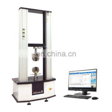 Universal Circuit Board Testing MachineUS$ 3,500 - 11,000MOQ: 1 SetBrand Name: HONGJINPlace of Origin: ChinaModel Number: HJ-D5Power: ElectronicHongjing Test Instrument Co., Ltd.
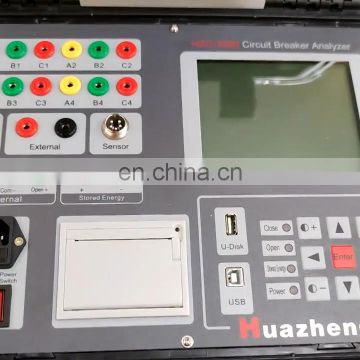 Circuit Breaker Test Machine 300a Circuit Breaker Test Equipment Electric dc Circuit Breaker Timing Test SetUS$ 1,000 - 3,300MOQ: 1 PieceBrand Name: HuaZhengPlace of Origin: Hebei, ChinaModel Number: hzC-3980Type: High VoltageHuazheng Electric Manufacturing (baoding) Co., Ltd.
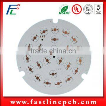 100% Test Alu PCB Led Circuit BoardUS$ 0.26 - 0.52MOQ: 1 PiecePlace of Origin: Guangdong, ChinaBrand Name: FastlineModel Number: FL852Base Material: AluminumShenzhen Fastline Electronic Material Co., Limited
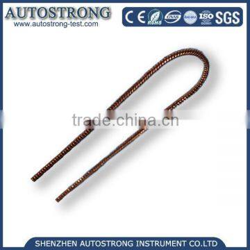 Safety Tester IEC60598 Test Chain for Short Circuit Protection TestUS$ 80 - 200MOQ: 1 PiecePlace of Origin: Guangdong, ChinaBrand Name: AUTOSTRONGModel Number: Auto-SYLPower: Other, MechanicalShenzhen Autostrong Instrument Co., Ltd.
 CALIBRE Digital Circuit Tester With 2 Piercing Test ProbesNegotiableMOQ: 300 SetsType: OtherVoltage: 6, 12, 24VPower: noneCertification: CEProjen Industrial Company Ltd.
 HY-CRI200 Common Rail System Test Bench Short-circuit ProtectionNegotiableMOQ: 1 SetPlace of Origin: Shandong, ChinaBrand Name: HaiyuModel Number: HY-CRI200Power: ElectronicTaian Haiyu Machinery Co., Ltd.
 Analog Circuit Trainer / Operational, Test, Amplifying Circuit / PCB Board, Basic Electronic Technology TrainingUS$ 10 - 1,000MOQ: 1 SetPlace of Origin: Shandong, ChinaBrand Name: XING KEModel Number: XK-EAP1Shandong Xingke Intelligent Technology Co., Ltd.
 CEM-1, CEM-3 E - Test Printed Circuit Board PCB Assembly Services For Automobile OEMNegotiableMOQ: 1 PieceBrand Name: ZoomtakPlace of Origin: ChinaModel Number: Zoomtak-PCBA-002Zoomtak Electronics Company
 Battery Forced Internal Short Circuit Testing MachineUS$ 4000 - 6000MOQ: 1 SetBrand Name: DeruiPlace of Origin: ChinaModel Number: DR-D201Power: OtherGuangdong Derui Testing Equipment Co., Ltd
 Lithium Battery Forced Internal Short Circuit Testing EquipmentUS$ 1299 - 3599MOQ: 1 SetBrand Name: LIKPlace of Origin: ChinaModel Number: LJ-1000APower: ElectronicGuangdong LIK Industry Co., Ltd
 Lithium Battery Short Circuit Test DeviceNegotiableMOQ: 1 SetBrand Name: China Electronic Product Reliability and Environmental Testing Research InstitutePlace of Origin: ChinaModel Number: 7210APower: ElectronicSaiRui(GZ) Test Equipment CO.,LTD
 Electronic Circuit Test BoardUS$ 150 - 290MOQ: 1 PiecePlace of Origin: Sichuan, ChinaBrand Name: WitoeasModel Number: WT9500AM1Chengdu Witoeas Technology Co., Ltd.
 Electronic Circuit Test BoardUS$ 1 - 150MOQ: 1000 SetsPlace of Origin: Guangdong, ChinaBrand Name: YQ-018Model Number: YQ-018WZBase Material: FR4Dongguan Qingxi Jin Huang Electronics Factory
 YCS 3060 DC Power Supply for Phone PCB Short Circuit RepairUS$ 35MOQ: 1 PieceTrademark: phonefixOrigin: ChinaShenzhen VIP FIXPHONE Technology Co., Ltd,
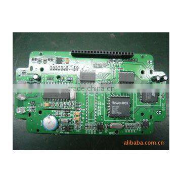 Professional Electronic Circuit Test BoardUS$ 1 - 100MOQ: 1 PiecePlace of Origin: Guangdong, ChinaBrand Name: HENGTAITOModel Number: HKT881Number of Layers: 4-LayerShenzhen Hengkaituo Sci-Tech Co., Ltd.
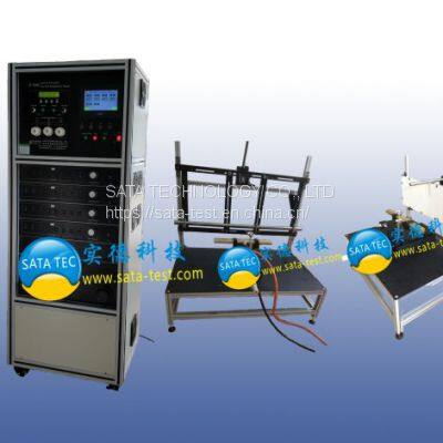 ST-7606 Wires and Cables Fire Resistance TesterUS$ 66666 - 66666MOQ: 1 SetBrand Name: SATAPlace of Origin: ChinaModel Number: ST-7606 seriesPower: ElectronicSata Technology Co., Ltd
 Battery Internal Safety Short Circuit Test MachineUS$ 1200 - 20800MOQ: 1 SetBrand Name: LIKPlace of Origin: ChinaModel Number: LJ-1000ACertification: ISO 9001Guangdong LIK Industry Co.,LTD
 Sourcing Manager is sourcing 12 Positions Single Phase Multifunction Energy Meter (Double Circuit) Test Bench2025-12-12 03:06:22
 Business Owner inquired about P1049A BNC test probe circuit test probe logic probe2025-12-10 18:08:19
 Import Coordinator submitted an RFQ for Ground rod&short-circuit test tools,High Voltage Portable Grounding Rod2025-12-10 09:24:41
 Purchasing Director inquired about 30A RMS Digital Earth Resistance Tester Clamp for Ground Circuit Testing2025-12-14 02:13:32
 Importer requested specs for Quality short circuit test pencil,electrical test pencil,tester2025-12-09 19:26:46
 Import Coordinator requested a quote for Ground rod&short-circuit test tools,High Voltage Portable Grounding Rod2025-12-12 20:51:41
 Importer requested a quote for Industrial laboratory Lithium Ion Battery cells Short-circuit testing cabinet6 hours ago
 Sourcing Manager verified certifications for 12 Positions Single Phase Multifunction Energy Meter (Double Circuit) Test Bench2025-12-10 16:58:47
 V-Checker Vchecker T701 Circuit Test PencilUS$ 29.99 - 29.99MOQ: 1 SetBrand Name: v-checkerPlace of Origin: ChinaModel Number: SO102V-checker.co.uk
 2 Layer Electronic Circuit Test BoardUS$ 1.2 - 10MOQ: 1 PiecePlace of Origin: Guangdong, ChinaBrand Name: HXModel Number: HX-009Base Material: FR4Shenzhen Huaxing PCBA Limited
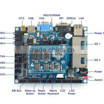 Fantastic Electronic Circuit Test Elevator Control BoardUS$ 100 - 255MOQ: 1 PieceD/C: IAC-A5D3X-KitPackage: BGAModel Number: IAC-A5D3X-KitBrand Name: QYZhejiang Qiyang Intelligent Technology Co., Ltd.
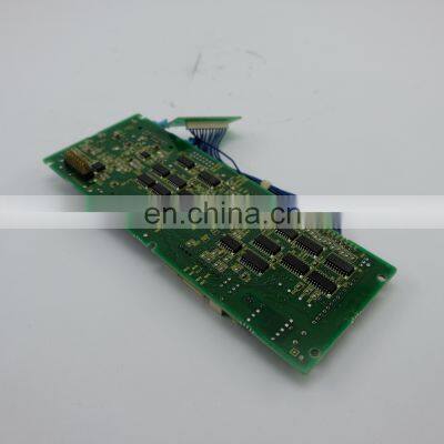
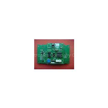 Custom Made PCB SMT Circuit BoardPrototyping , In Circuit Testing PCBANegotiableMOQ: 1 KilogramBrand Name: HUASWINPlace of Origin: ChinaModel Number: HSPCBA1062Huaswin Electronics Company Group
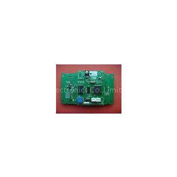 Custom Made PCB SMT Circuit BoardPrototyping , In Circuit Testing PCBANegotiableMOQ: 1 PieceBrand Name: HUASWINPlace of Origin: ChinaModel Number: HSPCBA1062Huaswin Electronics Co.,Limited.
 Custom Made PCB SMT Circuit BoardPrototyping , In Circuit Testing PCBANegotiableMOQ: 1 PieceBrand Name: HUASWINPlace of Origin: ChinaModel Number: HSPCBA1062Huaswin Electronics Company