Material
Other, Global universal model
Condition
Other, Global universal model
Task
Other, Global universal model
Mathematical Model
Other, Global universal model
Signal
Other, Global universal model
Customized
Non-Customized
Structure
Other, Global universal model
Operating Temperature
0℃~+40℃
Relative Humidity
5%-95% (non-condensing)
I. Overview
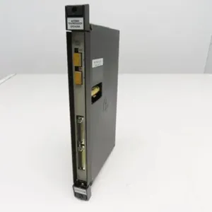
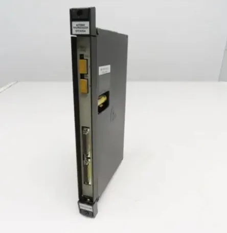
RELIANCE 0-57C405-C is a digital I/O drive module, whose core function is to act as a signal interaction bridge between the PLC system and field devices, undertaking the tasks of digital input signal acquisition and digital output control command transmission. Designed specifically for industrial automation control scenarios, this module is seamlessly compatible with Automax programmable logic controllers. With its 20-channel I/O interface configuration, 115V rated operating voltage, visualized status monitoring, and industrial-grade stability, it is widely used in scenarios such as DCS distributed control systems, servo drive systems, and linkage control of equipment in automated production lines. It serves as a key component to ensure the accurate transmission of industrial control signals.
II. Functional Features
Multi-channel I/O Configuration and Signal Interaction
It is equipped with 20 rectangular I/O connection ports (numbered A1/A2, B1/B2, C1/C2, D1/D2, E1/E2, F1/F2, G1/G2, H1/H2/H3, I1/I2/I3), supporting bidirectional transmission of digital input/output signals. It can connect multiple sensors (such as photoelectric switches, proximity switches) and actuators (such as relays, solenoid valves) simultaneously, meeting the requirements of multi-device linkage control.
It is compatible with industrial standard digital signals, featuring fast input signal response time and strong output signal driving capability. It can directly connect to field digital devices without additional signal conversion modules, simplifying the system architecture.
Visualized Status Monitoring and Fault Prompt
The module panel integrates 12 groups of status indicator lights (including A-I channel indicator lights, NET, AUX1, AUX2, M STATUS, RUN, RUN PERM, DFR, FMCR, RMCR, MCR). Different indicator lights correspond to different working states and fault types. When input/output signals are abnormal or the module malfunctions, the corresponding indicator lights will turn on, facilitating operation and maintenance personnel to quickly locate problem nodes.
The indicator lights are divided into 3 groups (4 lights per group) and designed by functional zones, which intuitively feed back channel signal status, module operation status, communication status, and protection mechanism triggering status, reducing the difficulty of on-site debugging and maintenance.
Industrial-grade Compatibility and Stability
Tailor-made for the Automax series PLCs, it achieves seamless connection with Automax programmable logic controllers, supporting system-level signal synchronization and command interaction to ensure the coherent execution of control logic.
Manufactured with industrial-grade components, it is suitable for the complex electromagnetic environment of industrial sites and has good anti-interference capability. It can operate stably for a long time under conventional industrial temperature and humidity conditions. The product has a warranty period of up to 12 months, and its reliability has been verified in industrial scenarios.
Convenient Configuration and Installation Design
The module panel is equipped with two groups of adjusting dials (one group marked with B/C/D/E/F/G, the other group marked with 1-3 on the left and 6-8 on the right), supporting on-site quick configuration of parameters such as I/O channel functions and signal types without complex software settings, improving debugging efficiency.
Adopting the standard industrial control module size design, it weighs about 2 pounds (approximately 0.91kg), and is compatible with the standard installation guide rails and racks of the Automax system. It is firmly installed and easy to disassemble and replace, saving cabinet space.
III. Technical Parameters

IV. Working Principle
The core working logic of RELIANCE 0-57C405-C is "Signal Acquisition → Status Feedback → Command Execution → Fault Monitoring", and the specific process is as follows:
Signal Acquisition and Transmission: Switch signals generated by field digital sensors (such as photoelectric switches, travel switches) are connected to the module through 20-channel I/O ports. The module converts the analog switch signals into digital signals recognizable by the PLC, and transmits them to the Automax PLC main controller after internal circuit processing.
Command Reception and Execution: According to the preset control logic, the PLC main controller sends digital output commands to the module. After receiving the commands, the module drives the output ports to control the actions of field actuators (such as relays, solenoid valves), realizing control functions such as equipment start-stop and linkage.
Status Monitoring and Feedback: The module real-time monitors its own operating status, the signal integrity of I/O channels, and the communication status with the PLC, and intuitively feeds back through 12 groups of indicator lights on the panel — for example, the RUN light is on indicating the module is operating normally, the NET light indicates the communication status, and the channel indicator lights reflect whether the signals of the corresponding ports are valid.
Fault Protection and Prompt: When detecting I/O channel short circuit, signal abnormality or communication interruption, the corresponding fault indicator lights (such as DFR, MCR) will turn on, and the module will feed back fault signals to the PLC at the same time, facilitating the system to trigger protection mechanisms in a timely manner and avoid equipment damage.
V. Operation Guide
1. Installation Steps
Installation Environment: Install in the standard control cabinet of the Automax system, away from strong electromagnetic interference sources such as frequency converters and high-voltage cables; reserve a heat dissipation gap of ≥10mm on both sides. The control cabinet must have dust-proof and ventilation functions, and the temperature and humidity of the working environment should comply with industrial standards (avoid condensation and extreme temperatures).
Mechanical Installation:
Confirm that the power supply of the control cabinet is cut off. Align the module with the standard guide rail or rack installation position of the Automax system, push it in and lock it with buckles or fixing screws to ensure the module is firmly installed without loosening, avoiding poor contact caused by vibration.
After installation, check whether the connection between the module and the PLC backplane is reliable to ensure the smoothness of the signal transmission channel.
Wiring Specifications:
Connect field devices according to the module port marks (A1/A2~I1/I2/I3). Connect sensor signal lines to input signals and actuator control lines to output signals, paying attention to the matching of positive and negative polarity and signal types.
Use shielded cables for wiring, and ground the shield layer at one end (grounding resistance ≤4Ω) to reduce electromagnetic interference; control the cable length according to industrial site specifications to avoid signal attenuation.
Connect the module working power supply to the standard 115VAC voltage. Before wiring, confirm that the power supply voltage is stable without excessive fluctuations.
2. Configuration and Debugging
Parameter Configuration: Perform on-site configuration through two groups of dials on the module panel. Select the corresponding gears (marked with B/C/D/E/F/G and 1-3/6-8 gears) according to control requirements, set the I/O channels to input or output mode, signal response mode and other parameters. After configuration, restart the module to make the parameters take effect.
Power-on Debugging:
Before the first power-on, check the correctness of the power wiring and I/O signal wiring to ensure there is no short circuit or reverse connection.
After powering on, observe whether the RUN light of the module is on (normal operating state) and whether the NET light indicates normal communication; trigger input signals one by one, check whether the corresponding channel indicator lights are on synchronously, and verify the accuracy of signal acquisition.
Send output commands through the PLC, observe whether the actuators act according to the commands, and check the status of the module output channel indicator lights at the same time to ensure the correct execution of commands; if the indicator lights are abnormal or the equipment does not respond, troubleshoot wiring or parameter configuration problems.
3. Operation and Maintenance
Status Monitoring: Real-time monitor the operating status through the indicator lights on the module panel:
Normal Status: The RUN light is always on, the NET light indicates normal communication, no fault indicator light is on, and the I/O channel lights switch synchronously with the signal status.
Fault Status: The corresponding fault indicator lights (such as DFR, MCR) are on. It is necessary to troubleshoot channel faults, communication interruptions or power supply abnormalities combined with the meaning of the indicator lights.
Regular Maintenance:
Monthly: Clean dust on the module surface and port contacts with dry compressed air, check whether the module is installed firmly, and whether the wiring terminals are loose or oxidized; observe the status of the indicator lights to ensure there is no abnormal alarm.
Every 6 Months: Fully check whether the insulation layer of the I/O wiring cables is damaged or aging, and whether the shield layer is reliably grounded; test the module signal response speed and output driving capability to ensure they meet the control requirements.
Annually: Back up the module configuration parameters (if supported), check whether the internal components of the module have signs of aging (such as capacitor bulging); if the module frequently malfunctions, replace the spare parts in a timely manner (the product warranty period is 12 months, and you can contact the supplier for after-sales service).
Notes:
Wiring, parameter configuration and module plugging/unplugging must be carried out in the power-off state. Live operation is prohibited to avoid short circuit or module damage.
It is forbidden to use the module beyond the rated voltage (115VAC) to avoid burning the internal circuit due to overvoltage; keep away from open flames and high-temperature radiation sources, and ensure the working environment complies with industrial standards.
For modules idle for a long time (more than 6 months), conduct insulation test and function verification before commissioning to ensure no abnormalities before connecting to the system.
4. Common Fault Troubleshooting









 Contact Platform Support
 Help Center