I. Product Overview
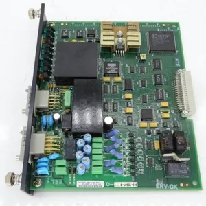
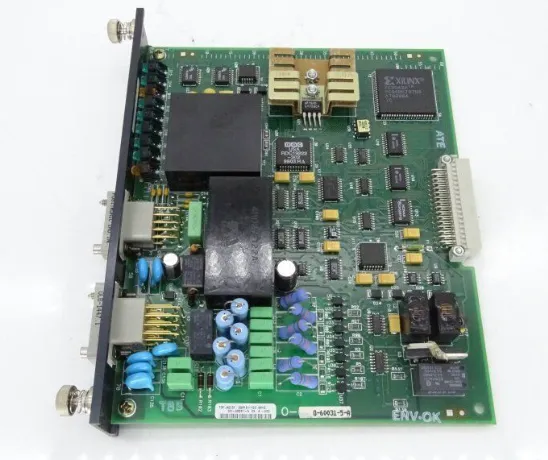
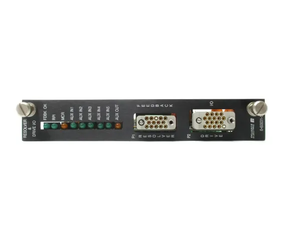
RELIANCE ELECTRIC 0-60031-5 is a control module, positioned as the core hub for signal processing and command execution in the system. It undertakes key tasks such as industrial field signal acquisition, logic operation, control command output, and equipment status monitoring. Leveraging RELIANCE ELECTRIC's profound industrial control technology accumulation, this product integrates a high-precision signal processing unit, stable logic control circuit, and reliable interface circuit. It enables seamless connection with PLCs, frequency converters, sensors, and various actuators, providing accurate and stable control support for heavy-duty industrial scenarios such as mine hoisting, machinery manufacturing, and energy & power.
Adopting stringent industrial-grade design standards, the product boasts excellent electromagnetic interference resistance, wide-temperature adaptability, and vibration resistance. It can operate stably in harsh industrial environments with dust, humidity, temperature fluctuations, and strong electromagnetic interference. Its compact modular structure is designed to meet the standardized installation requirements of industrial control cabinets, facilitating system integration and expansion. Widely applied in core scenarios such as heavy-duty equipment drive control and industrial process automation regulation, it serves as a key component to ensure the precise operation, safety, and stability of industrial control systems.

II. Functional Features
1. High-Precision Signal Processing with Excellent Control Accuracy
Equipped with a built-in high-precision signal acquisition and processing circuit, it can accurately collect analog (voltage, current) and digital signals from industrial fields with high sampling precision and fast response speed, effectively reducing interference and distortion during signal transmission. It has a complete signal conditioning function, which can filter, amplify, and standardize the collected raw signals, providing a reliable signal foundation for subsequent logic operations. Meanwhile, it supports precise control command output to ensure accurate regulation of actuators, meeting the stringent control accuracy requirements of heavy-duty industrial scenarios.
2. Strong Heavy-Duty Adaptability and Stable Operation
Adopting an optimized heavy-duty design, it has excellent heavy overload capacity and can operate stably for a long time under complex industrial working conditions. It is particularly suitable for the control scenarios of heavy-duty equipment such as mine hoists and heavy-duty conveyors. The product uses high-reliability components and reinforced circuit design inside, featuring outstanding shock and vibration resistance. It can withstand a multi-axis vibration environment of 10~500Hz with a peak acceleration of 2G, effectively resisting the impact of mechanical vibration in industrial fields on equipment operation, and ensuring the continuity and stability of the control link.
3. Industrial-Grade Environmental Adaptability and Superior Protection Performance
With a fully enclosed industrial-grade shell design, it has good dustproof and moisture-proof performance, which can effectively resist the erosion of dust and water vapor in industrial fields. The product supports a wide temperature range for operation and storage, and can run stably for a long time in extreme temperature environments of -20℃~+85℃. At the same time, it strictly complies with industrial electromagnetic compatibility standards and is equipped with a built-in EMI filter circuit, which can effectively resist electromagnetic interference generated by frequency converters, high-voltage equipment, etc., and avoid electromagnetic interference to other equipment during its own operation, ensuring stable operation in complex industrial environments.
4. Flexible Compatibility and Good System Integration
Equipped with rich standardized interfaces, it supports multiple industrial control signal types, and can flexibly adapt to PLCs, frequency converters, sensors, and actuators of different brands with strong compatibility. Adopting a modular design concept, it has standardized installation dimensions and can be directly embedded into the standard installation guide rail of industrial control cabinets, facilitating rapid system integration, expansion, maintenance, and replacement. It supports stable communication with the upper control system, enabling efficient uplink and downlink transmission of control commands, and helping build a full-link industrial automation control system.
5. Comprehensive Status Monitoring and Fault Protection
It has a complete equipment status monitoring and fault diagnosis function, which can real-time monitor the operating status of the module itself (power supply, circuit, interface) and the working status of connected equipment. When detecting problems such as signal abnormality, circuit fault, or connection interruption, it will immediately trigger the fault alarm mechanism. It feeds back fault information through status indicator lights and signal output, and has a fault isolation function, which can effectively avoid the spread of faults affecting the operation of the entire control system, providing accurate basis for operation and maintenance personnel to quickly locate and handle faults, and reducing system downtime.
6. Low-Power Stable Operation and Long Service Life
Adopting an efficient circuit design and low-power component selection, while ensuring high-performance operation, it effectively reduces equipment power consumption and temperature rise, reduces dependence on the cooling system, and extends the service life of components. The product has passed strict reliability tests and has long-life operation characteristics, which can meet the long-term continuous operation requirements of industrial scenarios and reduce equipment replacement and maintenance costs.
III. Technical Parameters

IV. Working Principle
The core working logic of the RELIANCE ELECTRIC 0-60031-5 control module is "Signal Acquisition → Signal Processing → Logic Operation → Command Output → Status Monitoring and Feedback". Through coordination with other components of the industrial control system, it completes the full-process control tasks. The specific working process is as follows:
Signal Acquisition: The module connects to sensors, transmitters, and other equipment in the industrial field through input interfaces, collects analog signals (such as temperature, pressure, speed) and digital signals (such as equipment start-stop status, fault signals) in real time, and converts on-site physical quantities into processable electrical signals.
Signal Processing: The collected raw electrical signals are sent to the built-in high-precision signal processing unit. The clutter interference is filtered out by the filter circuit, and the signals are standardized by the amplifier circuit, which are then converted into standard signals recognizable by the module's logic operation unit, ensuring the accuracy and reliability of the signals.
Logic Operation: The processed standard signals are transmitted to the logic operation unit. According to the preset control logic and parameter thresholds, the unit analyzes and calculates the signals, judges whether corresponding control actions need to be executed, and generates precise control commands.
Command Output: The control commands generated by logic operation are transmitted to actuators (such as contactors, frequency converters, solenoid valves, etc.) through output interfaces, driving the actuators to complete corresponding actions, and realizing precise regulation of industrial equipment or processes.
Status Monitoring and Feedback: The module real-time monitors its own operating status (power supply voltage, circuit working status, interface connection status) and the action feedback signals of actuators, and identifies abnormal working conditions through the built-in diagnostic algorithm. When an abnormality is detected, it immediately triggers the alarm mechanism, feeds back fault information through status indicator lights, and uploads fault signals to the upper control system at the same time. If a serious fault is detected, it will automatically cut off the output signal to avoid the expansion of faults and ensure system safety.
V. Installation Steps
Installation Environment Requirements
Select an installation location free from severe vibration and impact, away from high-temperature heat sources (heaters, boilers), strong electromagnetic interference sources (frequency converters, high-voltage busbars), and corrosive gases. Control the ambient temperature within -20℃~+85℃ and relative humidity within 5%~95% (no condensation), avoiding direct sunlight and rain splashing. The installation surface must be flat and firm to ensure the module is installed stably without loosening. Meanwhile, reserve sufficient ventilation and operation space to facilitate wiring and later maintenance.
Mechanical Installation Operation
Adopt standard DIN rail mounting: Align the module with the standard DIN rail in the industrial control cabinet, push it in smoothly along the rail direction until the module buckle is fully engaged with the rail, ensuring the module is installed firmly without shaking. Avoid collision with the module interface and shell during installation to prevent physical damage. When multiple modules are installed side by side, reserve a spacing of at least 5mm to ensure ventilation and heat dissipation effects.
Wiring Operation Specifications
Installation and wiring operations must be completed by professional and qualified industrial electrical technicians, strictly complying with industrial electrical safety specifications. Before operation, be sure to cut off the main power supply of the system and hang a "No Switching On" sign. Connect the power supply, signal input, and output cables in accordance with the wiring diagram specifications: Connect the power cable to the module's power terminal, confirm that the supply voltage matches the module's rated voltage (24VDC), correctly distinguish the positive and negative poles to avoid reverse connection that may damage the internal circuit. Connect the signal input cable to the signal input terminal, and select the appropriate specification cable according to the signal type (analog/digital). Connect the output cable to the output terminal to ensure reliable connection with the actuator. After completing all wiring, tighten the terminal screws one by one and check the correctness of the circuit to ensure no short circuit or loose connection.