

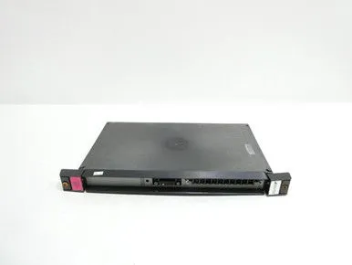
RELIANCE 0-57405-C I/O Analog Module

Related Products
-
 RELIANCE 0-57C402-C Output ModuleNegotiableMOQ: 1 Piece
 -
RELIANCE ELECTRIC S-D4006-D Digital I/O CardNegotiableMOQ: 1 Piece
-
RELIANCE ELECTRIC S-D4008-A Analog I/O ModuleNegotiableMOQ: 1 Piece
-
RELIANCE ELECTRIC WR-D4001-A Power Supply ModuleNegotiableMOQ: 1 Piece
-
RELIANCE ELECTRIC WR-D4005 Power Supply ModuleNegotiableMOQ: 1 Piece
I. Product Overview
RELIANCE 0-57405-C is an analog I/O driver module whose core function is to achieve accurate acquisition, conversion and control output of analog signals in industrial field. Specially designed for pairing with PMI drives, it can also be seamlessly integrated into industrial automation systems and DCS systems, providing reliable signal interaction support for scenarios such as process control, mechanical equipment control and energy monitoring.
II. Functional Features
Multi-channel Analog Signal Acquisition and Output Capability
Exclusive Adaptation to PMI Drives and System Compatibility
Industrial-grade Structural Design and High Reliability
Convenient Installation and Configuration Experience
III. Technical Parameters
IV. Working Principle
V. Operation Guide
1. Installation Steps
Installation Environment
Mechanical Installation
Wiring Operation
2. System Configuration
Parameter Initialization
Calibration Operation
Linkage Configuration
3. Operation and Maintenance
Daily Operation
Regular Maintenance
4. Common Fault Troubleshooting

Send Inquiry to This Supplier


You May Also Like
-
RELIANCE ELECTRIC 0-60007-2 Power Supply ModuleNegotiableMOQ: 1 Piece
-
RELIANCE ELECTRIC 0-60031-5 Power Supply ModuleNegotiableMOQ: 1 Piece
-
RELIANCE ELECTRIC 0-60021-4 Power Supply ModuleNegotiableMOQ: 1 Piece
-
RELIANCE ELECTRIC 0-60028-2 Power Supply ModuleNegotiableMOQ: 1 Piece
-
RELIANCE ELECTRIC 0-60029-1 Power Supply ModuleNegotiableMOQ: 1 Piece
-
RELIANCE ELECTRIC 0-60023-5 Power Supply ModuleNegotiableMOQ: 1 Piece
-
RELIANCE 0-57C407-4H Position Control ModuleNegotiableMOQ: 1 Piece
-
RELIANCE 0-57C404-1E Control ModuleNegotiableMOQ: 1 Piece
-
RELIANCE 0-57C400-A Communication ModuleNegotiableMOQ: 1 Piece
-
RELIANCE 0-57C406-E Display Control ModuleNegotiableMOQ: 1 Piece


