

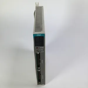
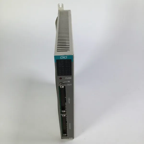
RELIANCE ELECTRIC S-D4006-D Digital I/O Card
Related Products
-
 RELIANCE ELECTRIC S-D4008-A Analog I/O ModuleNegotiableMOQ: 1 Piece
 -
RELIANCE ELECTRIC WR-D4001-A Power Supply ModuleNegotiableMOQ: 1 Piece
-
RELIANCE ELECTRIC WR-D4005 Power Supply ModuleNegotiableMOQ: 1 Piece
-
RELIANCE ELECTRIC 0-60007-2 Power Supply ModuleNegotiableMOQ: 1 Piece
-
RELIANCE ELECTRIC 0-60031-5 Power Supply ModuleNegotiableMOQ: 1 Piece
I. Product Overview
RELIANCE ELECTRIC S-D4006-D is a digital I/O control module whose core functions are to achieve high-speed acquisition and precise control output of digital signals in industrial sites. Specifically designed for discrete control scenarios of industrial automation systems, it can be seamlessly integrated into various PLC systems, DCS systems and industrial control platforms, providing stable digital signal interaction support for scenarios such as mechanical equipment automation, production line control and process monitoring.
II. Functional Features
Multi-channel Digital Signal Acquisition and Output
Strong Anti-interference Capability and Industrial-grade Stability
Wide Compatibility and Flexible Integration Capability
Convenient Installation and Operation & Maintenance Design
III. Technical Parameters
IV. Working Principle
V. Operation Guide
1. Installation Steps
Installation Environment
Mechanical Installation
Wiring Operation
2. System Configuration
Parameter Initialization
Communication Configuration
3. Operation and Maintenance
Daily Operation
Regular Maintenance
4. Common Fault Troubleshooting

Send Inquiry to This Supplier


You May Also Like
-
RELIANCE ELECTRIC 0-60021-4 Power Supply ModuleNegotiableMOQ: 1 Piece
-
RELIANCE ELECTRIC 0-60028-2 Power Supply ModuleNegotiableMOQ: 1 Piece
-
RELIANCE ELECTRIC 0-60029-1 Power Supply ModuleNegotiableMOQ: 1 Piece
-
RELIANCE ELECTRIC 0-60023-5 Power Supply ModuleNegotiableMOQ: 1 Piece
-
RELIANCE 0-57C407-4H Position Control ModuleNegotiableMOQ: 1 Piece
-
RELIANCE 0-57C404-1E Control ModuleNegotiableMOQ: 1 Piece
-
RELIANCE 0-57C400-A Communication ModuleNegotiableMOQ: 1 Piece
-
RELIANCE 0-57C406-E Display Control ModuleNegotiableMOQ: 1 Piece
-
RELIANCE 0-57411-2C Resolver Input ModuleNegotiableMOQ: 1 Piece
-
RELIANCE 0-57C401-2 Processing ModuleNegotiableMOQ: 1 Piece


