Material
Other, Global universal model
Condition
Other, Global universal model
Task
Other, Global universal model
Mathematical Model
Other, Global universal model
Signal
Other, Global universal model
Customized
Non-Customized
Structure
Other, Global universal model
Operating Temperature
-40℃~+70℃
Relative Humidity
5%-95% (non-condensing)
I. Overview
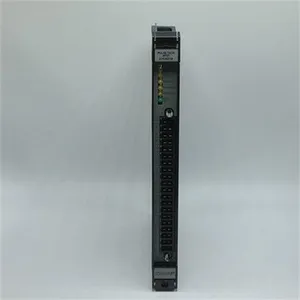
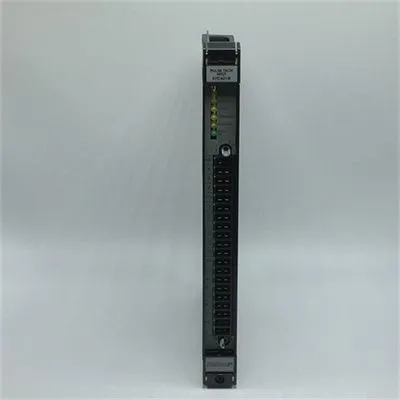
RELIANCE 57C652 is a digital I/O expansion module whose core function is to serve as a signal expansion unit of the PLC system, enhancing the high-speed acquisition capability of digital input signals and the precise execution capability of digital output commands. Designed specifically for medium and large-scale industrial automation scenarios, this module is seamlessly compatible with all series of Automax programmable logic controllers. With its 32-channel high-density I/O configuration, wide voltage adaptability, industrial-grade anti-interference design, and visualized status monitoring, it is widely applied in scenarios such as large-scale DCS distributed control systems, multi-device linkage in automated production lines, supporting control of industrial robots, and signal interaction in servo drive systems. It is a key expansion component for improving the signal processing capacity and response speed of industrial control systems.
II. Functional Features
High-Density I/O Channels and Flexible Signal Interaction
It is equipped with 32 digital I/O channels (divided into 16 inputs + 16 outputs, or configurable to mixed I/O mode via dials). The channels are grouped and numbered (e.g., CH1-CH16 for inputs, CH17-CH32 for outputs), supporting simultaneous connection of 16 digital sensors (such as photoelectric switches, proximity switches, travel switches, etc.) and 16 actuators (such as relays, solenoid valves, contactors, etc.), which meets the multi-device coordinated control requirements of medium and large-scale systems.
The input signal response time is ≤1ms, and the output signal driving capacity reaches 2A per channel (for resistive loads). It supports the connection of industrial-standard NPN/PNP sensors without additional signal conversion modules, enabling direct connection to field devices and simplifying system wiring and architecture design.
Wide Voltage Adaptability and Industrial-Grade Anti-Interference
The input voltage supports a wide range of 12-24VDC (compatible with PNP/NPN polarity switching), and the output voltage is compatible with dual specifications of 12-24VDC/220VAC. It adapts to the power supply requirements of different field devices without additional voltage regulation components, improving the module's versatility.
It features enhanced Electromagnetic Compatibility (EMC) design and has passed IEC 61000-4 anti-interference tests (ESD ±8kV, surge ±2kV, radio frequency interference 10V/m). Adopting differential signal transmission and shield grounding design, it can resist high-frequency electromagnetic radiation, power grid fluctuations and other interferences in industrial sites, ensuring the stability of signal transmission.
Visualized Status Monitoring and Fault Diagnosis
The module panel integrates 36 sets of status indicator lights, including 32 independent I/O channel indicator lights (green for input channels, red for output channels), a module running indicator light (RUN, green), a communication status indicator light (COM, yellow), and a fault alarm indicator light (FAULT, red). It intuitively feeds back the signal status of each channel, the module's running status, and the integrity of the communication link.
It supports fault self-diagnosis function. When a channel short circuit, signal abnormality or communication interruption occurs, the FAULT light stays on and locks the fault information. Combined with the status of channel indicator lights, operation and maintenance personnel can quickly locate the fault point and shorten troubleshooting time.
Seamless Compatibility and Convenient Expansion
Tailor-made for the Automax series PLCs, it achieves seamless connection via the system backplane bus and supports multi-module cascade expansion (up to 8 modules can be cascaded, expanding to 256 I/O channels), meeting the signal processing capacity requirements of large-scale control systems. The expansion process does not require modifying the core control program, but only simple configuration of system parameters.
Adopting a standardized snap-in mounting design, it is compatible with the standard guide rails and racks of the Automax system. The single module has a compact size (compatible with dual-slot installation positions) and weighs about 1.2kg, featuring convenient installation and disassembly and saving cabinet space.
High Reliability and Long-Term Stable Operation
It uses industrial-grade high-temperature resistant components (operating temperature: -40℃~+70℃) and sealed protection design (IP20), with a humidity adaptation range of 5%-95% (non-condensing) and a Mean Time Between Failures (MTBF) of ≥200,000 hours. It can operate stably for a long time in harsh industrial environments such as high temperature, high humidity and heavy dust.
It has built-in channel overcurrent protection and short-circuit protection mechanisms. When an output channel is overloaded or short-circuited, it automatically cuts off the power supply of the faulty channel without affecting the operation of other channels and the module as a whole, protecting the module and field devices from damage.

III. Technical Parameters
IV. Working Principle
The core working logic of RELIANCE 57C652 is "Signal Acquisition → Signal Processing → Command Execution → Status Feedback → Fault Diagnosis", and the specific process is as follows:
Signal Acquisition: Switch signals generated by field digital sensors (such as photoelectric switches, travel switches) are connected to the module through 32 I/O channels. The input channels convert the analog switch signals into standard digital signals (0/1) recognizable by the PLC, and filter out interference signals through internal isolation circuits to ensure signal purity.
Signal Transmission and Processing: The collected digital signals are transmitted to the PLC main controller via the Automax system backplane bus. The main controller performs arithmetic processing on the signals according to the preset control logic and generates corresponding digital output commands.
Command Execution: The output commands issued by the PLC main controller are transmitted to the module via the bus. After receiving the commands, the module's output channels drive the corresponding actuators (such as relays, solenoid valves) to act, realizing functions such as equipment start-stop, speed regulation and linkage control.
Status Feedback: The module real-time monitors the signal status of each I/O channel, its own running status and the communication status with the PLC, and intuitively feeds back the information through the panel indicator lights — the corresponding green light is on when an input channel has a signal, the corresponding red light is on when an output channel executes a command, the RUN light staying on indicates the module is running normally, and the COM light flashing indicates normal communication.
Fault Diagnosis and Protection: The module has a built-in fault monitoring circuit that real-time detects channel current, voltage and communication links. When a channel short circuit, overload, signal abnormality or communication interruption is detected, it immediately triggers the protection mechanism (cuts off the power supply of the faulty channel), the FAULT light stays on and feeds back the fault code to the PLC, facilitating rapid system response and fault location.
V. Operation Guide
1. Installation Steps
Installation Environment: Install in the standard control cabinet of the Automax system, away from strong electromagnetic interference sources such as frequency converters and high-voltage cables; reserve a heat dissipation gap of ≥15mm on both sides. The control cabinet must have ventilation or forced heat dissipation functions to avoid performance degradation of the module due to poor heat dissipation; the installation position should facilitate the observation of indicator lights and maintenance operations.
Mechanical Installation:
Confirm that the main power supply of the control cabinet is cut off. Align the module with the dual-slot installation position of the standard guide rail of the Automax system, push it in and lock it with the buckles on both sides to ensure the module is firmly attached to the guide rail without loosening; when cascading multiple modules, insert the expansion modules into adjacent slots in sequence to ensure reliable bus connection between modules.
After installation, check whether the connection contacts between the module and the system backplane are clean and free of oxidation to ensure the smoothness of the signal transmission channel.
Wiring Specifications:
Input Wiring: Connect the sensor signal lines according to the module terminal marks (CH1-CH16), distinguishing PNP/NPN polarity (configured via the polarity switching dial on the side of the module). Use 1.0mm² shielded copper core cables for input wiring, ground the shield layer at one end (grounding resistance ≤4Ω), and keep the cable length ≤100m (to avoid signal attenuation).
Output Wiring: Connect the actuator control lines according to the terminal marks (CH17-CH32), select 12-24VDC or 220VAC power supply according to the rated voltage of the actuator. Use 1.5mm² copper core cables for output wiring, and configure additional relay amplification drives for high-power actuators; pay attention to the positive and negative polarity during wiring to avoid module damage caused by reverse connection.
Grounding Treatment: Reliably connect the module's grounding terminal to the protective ground and system signal ground of the control cabinet to form a single-point grounding system with a grounding resistance ≤4Ω, enhancing anti-interference capability.
2. Configuration and Debugging
Parameter Configuration:
Configure the I/O mode (16 inputs + 16 outputs or mixed mode) and input signal polarity (PNP/NPN) via the dial on the side of the module; when cascading multiple modules, set the module address (0-7) via the dial to ensure no duplicate addresses.
Connect the Automax PLC programming software, add the 57C652 module in the system configuration interface, set the module address and I/O channel mapping relationship, save the configuration and download it to the PLC main controller, then restart the system to make the configuration take effect.
Power-On Debugging:
Before the first power-on, check whether the power supply voltage, wiring polarity and module address configuration are correct to ensure there is no short circuit or reverse connection.
After powering on, observe whether the module's RUN light stays on (green) and the COM light flashes (normal communication). If the FAULT light stays on, cut off the power immediately and troubleshoot wiring or configuration problems.
Input Signal Test: Trigger the sensors of CH1-CH16 input channels one by one, observe whether the corresponding input indicator lights are on synchronously, and monitor the input signal status through the programming software to verify the acquisition accuracy.
Output Signal Test: Issue output commands through the programming software, observe whether the indicator lights of CH17-CH32 output channels are on and whether the actuators act according to the commands to verify the reliability of command execution; record the channel response time during the test to ensure it is ≤1ms.
Cascade Test (for multiple modules): Issue cross-module I/O interaction commands, check whether the signal transmission between modules is normal without delay or loss.
3. Operation and Maintenance
Status Monitoring: Real-time monitor the running status through the module panel indicator lights and programming software:
Normal Status: The RUN light stays on, the COM light flashes, the FAULT light is off, and the input/output channel lights switch synchronously with the signal status.
Fault Status: The FAULT light stays on. Locate the fault type and position by combining the fault codes read by the programming software (such as channel short-circuit code, communication interruption code).
Regular Maintenance:
Monthly: Clean dust on the module surface and terminal contacts with dry compressed air, check whether the module is installed firmly, and whether the wiring terminals are loose or oxidized; observe the status of indicator lights to ensure no abnormal alarms.
Every 6 Months: Fully check whether the insulation layer of I/O wiring cables is damaged or aging, and whether the shield layer is reliably grounded; test the input signal response time and output driving capacity to ensure they meet the parameter requirements; when cascading multiple modules, check whether the bus connection between modules is intact.
Annually: Back up the module configuration parameters and system programs; check whether the internal components of the module have signs of aging (such as capacitor bulging, heat sink loosening); if the module malfunctions frequently, replace the spare parts in a timely manner (it is recommended to contact Rockwell Automation official after-sales service).
Notes:
Wiring, parameter configuration and module plugging/unplugging must be carried out in the power-off state. Live operation is prohibited to avoid short circuit or module damage.
It is forbidden to use the module beyond the rated voltage and current range. High-power actuators must be equipped with relays to avoid burnout of output channels due to overload.
For modules idle for a long time (more than 6 months), conduct insulation tests and function verification before commissioning to ensure no abnormalities before connecting to the system.
4. Common Fault Troubleshooting