Material
Other, Global universal model
Condition
Other, Global universal model
Task
Other, Global universal model
Mathematical Model
Other, Global universal model
Signal
Other, Global universal model
Customized
Non-Customized
Structure
Other, Global universal model
Operating Temperature
-20℃~40℃
Relative Humidity
5%-95% (non-condensing)
Dimensions
450mm×180mm×180mm
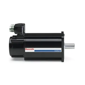
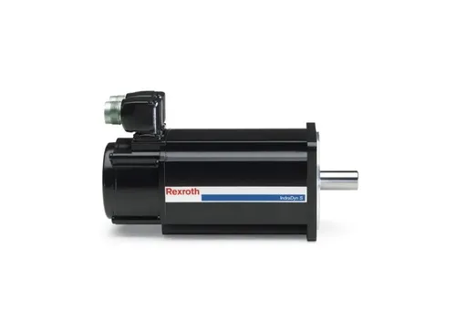
REXROTH MDD112D-N030-N2M-130GA0 is a medium-power permanent magnet synchronous servo motor in the MDD series. As an executive unit for 3kW-class precision motion control, it is mainly adapted to medium-power scenarios such as CNC machine tools, machining centers, automated assembly lines, packaging machinery, material handling equipment, and metallurgical auxiliary equipment. It undertakes core tasks including high-precision trajectory execution, high-dynamic speed output, and stable torque supply.
Its core advantage lies in the adoption of a high-performance permanent magnet synchronous design, combined with precision rotor dynamic balance and an optimized stator winding structure. While achieving high power density, it ensures the dual performance of high torque at low speeds and stable operation at high speeds. This motor can be perfectly matched with Rexroth HDS series and CSB series servo drives to form an integrated "drive-motor" control solution, providing solid executive support for the high-precision and high-stability operation of equipment. It is the preferred executive component for medium-power precision motion control scenarios.
I. Technical Parameters
1. Basic Power and Speed Parameters
Rated power: 3.0kW; rated speed: 1500rpm; rated torque: 19.1N·m (calculated according to the torque formula T=9550P/n, T=9550×3/1500≈19.1N·m).
Peak power: 9.0kW (duration 3s); peak torque: 57.3N·m (under peak power), which can meet the instantaneous overload requirements of medium-power loads.
Base speed: 1500rpm; maximum speed under field weakening: 3000rpm. In the field-weakening range, speed can be increased while maintaining stable power.
Speed fluctuation rate: ≤±0.05% (at rated speed), ensuring stability during high-speed operation.
2. Electrical Performance Parameters
Rated voltage: 380V (three-phase AC); rated current: 6.5A; power factor: ≥0.95 (under rated load); motor efficiency: ≥94% (IE3 high-efficiency class). It complies with international energy efficiency standards and reduces energy loss.
Stator winding insulation class: Class F; insulation resistance: ≥1000MΩ (tested with 2500V DC), which can withstand high-temperature working conditions of 155℃.
Rotor: Adopts high-performance neodymium-iron-boron (NdFeB) permanent magnets, with residual magnetic density ≥1.2T and coercivity ≥1100kA/m, ensuring magnetic field stability and long-term operation reliability.
3. Structural and Installation Parameters
Frame size: 112D; adopts cast iron housing design with excellent heat dissipation performance.
Overall dimensions (length×width×height): 450mm×180mm×180mm (including encoder and terminal box); shaft extension diameter: 30mm; shaft extension length: 50mm; adopts flat key connection (key width 8mm).
Installation methods: Supports foot mounting (B3) and flange mounting (B5/B14), adapting to the installation layouts of different equipment.
Cooling method: Self-fan cooling (IC411), equipped with an optimally designed cooling fan and heat dissipation fins. It ensures that the temperature rise is ≤80K during continuous operation under rated load (at an ambient temperature of 40℃).
4. Feedback and Adaptation Parameters
Standard configuration: 130-series incremental encoder (1024 lines, TTL signal); optional 23-bit multi-turn absolute encoder (EnDat 2.2 interface), supporting power-off position memory function.
Encoder protection class: IP65, adapting to harsh industrial environments.
Adaptable drive range: Covers Rexroth HDS03 series (3kW~7.5kW) and CSB03 series (3kW~5.5kW), and is also compatible with third-party medium-power servo drives that meet the IEC 61131-2 standard.
Wiring method: Terminal-type terminal box (top-mounted, rotatable by 90° to adjust direction), facilitating on-site wiring.
5. Environmental and Reliability Parameters
Operating temperature: -20℃~40℃ (without forced cooling), -20℃~55℃ (with forced cooling); storage temperature: -40℃~70℃.
Relative humidity: 5%~95% (non-condensing).
Protection class: IP54 (housing), IP65 (encoder), adapting to industrial environments with dust and humidity.
Mechanical life: ≥20,000 hours (under rated working conditions); bearing life: ≥15,000 hours (grease lubrication, maintenance-free period of 8,000 hours).
Dynamic balance class: G2.5 (at 1500rpm); vibration velocity during operation: ≤2.8mm/s, reducing the risk of equipment resonance.
II. Functional Features
1. Permanent Magnet Synchronous Structure + High-Efficiency Design to Reduce Energy Loss
Adopts a rotor design with high magnetic energy product NdFeB permanent magnets, no excitation winding is required, eliminating excitation loss. The motor efficiency is increased to over 94% (IE3 class), and energy consumption is reduced by 15%~20% compared with traditional asynchronous servo motors.
Optimized stator winding arrangement (short-pitch distributed winding) reduces copper loss and iron loss. The power factor is increased to over 0.95, reducing the reactive power burden of the drive.
The rotor adopts an integrated permanent magnet inlay structure, avoiding the risk of permanent magnet falling off during high-speed operation. At the same time, it reduces reluctance torque and improves operation stability.
2. High Torque Density + Wide Speed Range Operation to Adapt to Diverse Scenarios
Through optimized electromagnetic design, the torque density reaches 2.8N·m/kg, achieving a rated power of 3kW with a 112 frame size. The power is increased by 30% compared with asynchronous motors of the same size.
It can output a stable torque of 19.1N·m at a rated speed of 1500rpm, meeting the low-speed and high-torque requirements of CNC machine tool feed axes and assembly equipment actuators.
Supports field-weakening speed increase to 3000rpm, maintaining stable power in the high-speed range, and adapting to the high-speed operation needs of packaging machinery and material handling equipment.
The speed fluctuation rate is ≤±0.05%, ensuring speed stability during high-speed operation and improving processing or conveying precision.
3. Precision Structure + Reliable Protection to Extend Service Life
Adopts G2.5-class dynamic balance technology, performing double dynamic balance treatment on rotating components such as rotors and fans. The vibration velocity during operation is ≤2.8mm/s, reducing bearing wear and equipment resonance noise.
The housing is made of cast iron, with a corrosion-resistant coating on the surface. Combined with the IP54 protection class, it can effectively resist dust, oil pollution, and slight liquid erosion.
The encoder adopts an IP65 protection design and is equipped with a sealed connector, adapting to harsh environments such as machine tool coolant and packaging industry dust.
The bearings are imported high-precision deep groove ball bearings, filled with long-acting grease. The maintenance-free period reaches 8,000 hours, reducing operation and maintenance costs.
4. Flexible Adaptation + Convenient Installation to Optimize Integration Efficiency
Adopts a standardized frame design, supporting multiple installation methods such as B3, B5, and B14. The shaft extension size conforms to ISO standards, and it can directly replace motors of other brands with the same specification, reducing the difficulty of equipment upgrading and transformation.
The terminal box supports 360° rotation (positioning every 90°), and the direction can be adjusted according to the on-site wiring space, improving installation flexibility.
Realizes "plug-and-play" with Rexroth servo drives. The drive can automatically identify parameters through the motor nameplate without manual input, reducing debugging time by 60%.
Optional encoders with different resolutions and brakes (power-off brake, braking torque 40N·m) are available, adapting to scenarios with different control precision and safety requirements.

III. Working Principle
1. Magnetic Field Establishment Stage
The motor rotor has built-in high-performance NdFeB permanent magnets, which can establish a constant magnetic field without external excitation, forming the main rotor magnetic field. When the servo drive inputs three-phase AC to the motor stator winding, the three-phase current generates a rotating magnetic field in the stator core. The speed of the rotating magnetic field (synchronous speed) is determined by the input current frequency, and the formula is n₀=60f/p (n₀ is the synchronous speed, f is the current frequency, and p is the number of motor pole pairs).
2. Torque Generation and Operation Stage
An electromagnetic force is generated between the stator rotating magnetic field and the rotor permanent magnet magnetic field, pushing the rotor to rotate synchronously with the stator rotating magnetic field, thereby outputting mechanical torque. The motor speed is consistent with the stator rotating magnetic field speed (synchronous operation), with no slip loss, and the efficiency is significantly higher than that of asynchronous motors. The servo drive realizes precise control of motor speed and torque by adjusting the frequency and amplitude of the input current—adjusting the frequency can change the speed of the rotating magnetic field, thereby controlling the motor speed; adjusting the current amplitude can change the strength of the rotating magnetic field, thereby controlling the output torque.
3. Closed-Loop Feedback Regulation Stage
The encoder at the end of the motor collects the rotor speed and position signals in real time and transmits them to the servo drive through signal cables. The drive compares the actual speed and position signals fed back by the encoder with the target signals sent by the upper controller to calculate the deviation value. Based on the deviation value, it adjusts the frequency and amplitude of the current output to the stator winding, and corrects the motor speed and position in real time to ensure that the motor operation state accurately follows the target command. When the load changes, the drive adjusts the output torque in a timely manner by detecting changes in the stator current to maintain stable speed.
4. Field-Weakening Speed Increase Stage
When the motor speed reaches the base speed (1500rpm), if further speed increase is required, the drive will reduce the excitation current of the stator winding and use the motor leakage flux linkage to achieve field-weakening control. In the field-weakening state, the speed of the stator rotating magnetic field increases, and the rotor accelerates synchronously under the action of electromagnetic force until it reaches the maximum field-weakening speed (3000rpm). During this process, the motor output power basically remains at the rated power, and the torque decreases inversely with the increase in speed, meeting the needs of high-speed and light-load scenarios.
IV. Common Faults and Solutions
Fault 1: Motor Vibrates During Operation After Startup, and Speed Is Unstable
Possible Causes
Mismatch between motor and drive parameters (e.g., incorrect number of pole pairs setting);
Damaged rotor dynamic balance;
Jammed or eccentric mechanical load;
Encoder signal interference;
Excessive power supply voltage fluctuation.
Solutions
Check the motor parameter settings in the drive, ensure that the number of pole pairs, rated power, rated speed, etc., are consistent with the motor nameplate, and re-execute motor parameter self-tuning;
Check whether the permanent magnets of the motor rotor are loose or fall off due to long-term operation; if so, return the motor to the factory for repair;
Manually rotate the motor shaft to confirm there is no jamming, check whether the mechanical load is installed eccentrically, and re-calibrate the load concentricity;
Check whether the encoder cable shielding is in good condition, re-tighten the encoder connector, avoid parallel wiring with power cables, and install a signal isolator if necessary;
Use a multimeter to detect the input power voltage, ensure it is within the range of 380V±10%, and install a voltage stabilizer if the voltage fluctuates greatly.
2. Fault 2: Insufficient Torque Under Rated Load, Unable to Drive the Load
Possible Causes
The drive output current does not reach the rated value;
Demagnetization of motor permanent magnets;
Inter-turn short circuit of stator winding;
Low mechanical transmission efficiency (e.g., jammed gears, poor screw lubrication);
Improper matching between motor and load.
Solutions
Check the operating current through the drive monitoring interface; if it does not reach the rated 6.5A, check whether the drive torque limit parameter is too low and re-adjust the parameter;
Detect the motor back EMF (rotate the motor in the power-off state and measure the stator winding terminal voltage with a multimeter); if the back EMF is lower than the standard value (about 220V/1500rpm), it indicates demagnetization of the permanent magnet, and the permanent magnet needs to be replaced by returning the motor to the factory;
Use a megohmmeter to detect the insulation resistance of the stator winding; if the phase-to-phase resistance difference is too large, there may be an inter-turn short circuit, and the winding needs to be repaired by returning the motor to the factory;
Check the mechanical transmission mechanism, clean the gears and screws, and add special grease to eliminate jamming;
Check the motor rated torque and load requirements; if the load torque exceeds 19.1N·m, replace the motor with a higher power one.
3. Fault 3: Encoder Fault Alarm, Drive Cannot Control Normally
Possible Causes
Broken encoder cable or poor contact;
Encoder power failure (usually 5V DC);
Internal damage of the encoder;
Loose or misaligned connection between the motor shaft and the encoder shaft;
Signal distortion caused by electromagnetic interference.
Solutions
Check the continuity of the encoder cable, focus on checking whether the pins at the connector are loose or oxidized, replace the damaged cable and re-tighten the connector;
Use a multimeter to detect the encoder power supply, ensure the voltage is stably within 5V±0.2V; if the power supply is abnormal, repair the drive power supply module;
Disconnect the encoder from the drive, manually rotate the motor shaft, and use an oscilloscope to detect the encoder output waveform; if the waveform is disordered or there is no output, the encoder is damaged and needs to be replaced;
Remove the encoder end cover, check whether the coupling between the encoder and the motor shaft is loose or misaligned, and re-install and calibrate it;
Add a shielding layer to the encoder cable and ground it at one end (grounding resistance ≤4Ω), and keep it away from strong interference sources such as inverters and high-power contactors.
4. Fault 4: Motor Heats Severely During Operation, Temperature Rise Exceeds 80K
Possible Causes
Long-term overload of the load (operating current exceeds 6.5A);
Damaged cooling fan or blocked heat dissipation fins;
Poor ventilation in the motor installation environment;
Inter-turn short circuit of the stator winding;
Increased friction due to damaged bearings.
Solutions
Monitor the operating current; if it exceeds the rated value for a long time, check whether the load is too heavy, optimize the load or replace the motor with a higher power one;
Check whether the cooling fan rotates normally, clean the dust on the surface of the heat dissipation fins, and ensure the heat dissipation channel is unobstructed;
Improve the installation environment, add ventilation fans or heat dissipation holes to the control cabinet, and avoid operating the motor in a closed space;
Detect the phase-to-phase resistance and insulation resistance of the stator winding, identify inter-turn short circuit faults, and return the motor to the factory for repair;
Manually rotate the motor shaft; if significant resistance is felt, the bearing may be damaged, and replace it with an imported bearing of the same model (SKF or NSK brand is recommended).









 Contact Platform Support
 Help Center