Material
Other, Global universal model
Condition
Other, Global universal model
Task
Other, Global universal model
Mathematical Model
Other, Global universal model
Signal
Other, Global universal model
Customized
Non-Customized
Structure
Other, Global universal model
Operating Temperature
0℃~40℃
Relative Humidity
5%-95% (non-condensing)
Dimensions
210mm × 80mm × 80mm
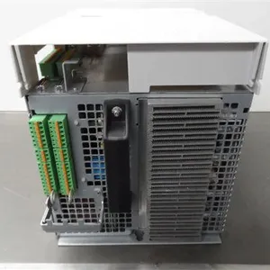
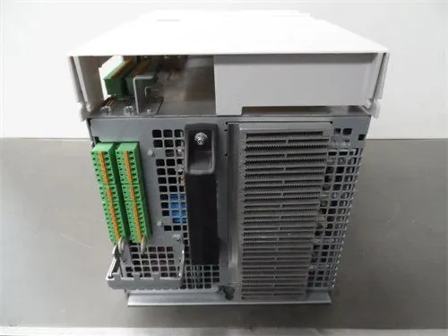
The Rexroth DKC02.3-200-7-FW is a compact servo drive. With its precise speed and torque control capabilities, compact structural design, and versatile communication compatibility, it is widely used in high-precision motion control fields such as machine tool manufacturing, automated production lines, packaging machinery, printing machinery, and electronic equipment manufacturing. It undertakes the tasks of power driving, motion closed-loop control, and status monitoring for servo motors. Its core technical advantages lie in the adoption of advanced vector control algorithms and digital signal processing architecture, enabling high-precision position, speed, and torque three-mode control of servo motors. It is seamlessly compatible with servo motors such as the Rexroth MSM series, forming a full closed-loop motion control chain of "command input - precise driving - status feedback - dynamic correction". It provides stable and reliable core support for high-speed and high-precision motion control of industrial equipment, and is a benchmark driving component in mid-to-high-end motion control systems.
Technical Parameters
1.1 Core Driving Parameters
Adopts a three-phase permanent magnet synchronous motor driving architecture. The rated output current is 20A (rms), and the peak output current is 60A (rms, with a duration of 3s).
The applicable motor rated power range is 7.5kW~11kW (adapted according to motor pole number and speed), and the maximum output power can reach 15kW (peak working condition).
Supports a speed control range of 0~6000rpm (for 4-pole motors), with a speed control accuracy of ±0.01% (at rated speed).
The torque control accuracy is ±0.5% (at rated torque). The position control accuracy depends on the motor encoder resolution; when used with a 17-bit absolute encoder, the positioning accuracy can reach ±0.001°.
The dynamic response time is ≤1ms (speed step response), ensuring fast tracking of command changes.
1.2 Control and Feedback Parameters
Adopts vector control (FOC) and servo control algorithms, supporting seamless switching between position, speed, and torque control modes.
Supports connection of various feedback devices such as incremental encoders (TTL/HTL), absolute encoders (SSI, EnDat 2.2), and resolvers. The encoder signal interface supports 5V differential signals and 12V push-pull signals.
Equipped with an electronic gearbox function, the electronic gear ratio range is 1:1000~1000:1, supporting master-slave control and synchronous control.
Built-in PID regulator and feedforward control algorithm; PID parameters can be adaptively tuned via software. It supports vibration suppression function, with an adjustable suppression frequency range of 5Hz~500Hz.
1.3 Input, Output and Communication Parameters
2 channels of analog input, supporting 0~10V DC or -10V~+10V DC voltage signals, with an input impedance of ≥100kΩ and a resolution of 12 bits.
2 channels of analog output, supporting 0~10V DC voltage signal output, with an output impedance of ≤100Ω.
8 channels of digital input (PNP/NPN optional), with a response time of ≤10μs, used for control signal enable, start/stop, position triggering, etc.
4 channels of digital output (relay/transistor output optional), used for fault alarm, operation status feedback, etc.
The communication interface supports mainstream industrial buses such as PROFIBUS DP, EtherCAT, and CANopen. The bus data update cycle is ≤100μs, supporting real-time motion control command transmission and equipment status monitoring.
1.4 Power Supply and Power Consumption Parameters
The input power supply is three-phase AC 380V~480V, with a voltage fluctuation range of ±10% and adaptive frequency of 50Hz/60Hz.
Built-in braking unit (external braking resistor required), with a braking power of ≥10kW and an applicable braking resistor range of 50Ω~100Ω.
The rated power consumption of the drive is ≤12kW (when running at full load with an 11kW motor), and the standby power consumption is ≤500W.
Equipped with power phase sequence error protection, undervoltage protection (≤320V AC), and overvoltage protection (≥530V AC) functions to ensure power supply safety.
1.5 Environmental and Reliability Parameters
Operating temperature range: 0℃~40℃ (without forced cooling), 0℃~55℃ (with forced cooling); storage temperature range: -20℃~80℃.
Relative humidity: 10%~90% (no condensation).
Protection class: IP20 (panel mounting), IP54 (optional protective housing).
Vibration resistance complies with IEC 60068-2-6 standard (10Hz~500Hz, acceleration 2g); shock resistance complies with IEC 60068-2-27 standard (10g, 11ms half-sine wave).
Mean Time Between Failures (MTBF) ≥500,000 hours, supporting 24/7 continuous operation.
Functional Features
2.1 Vector Closed-Loop Precise Control, Leading Motion Performance in the Industry
Adopts the Field-Oriented Control (FOC) algorithm. By decoupling and controlling the excitation component and torque component of the motor stator current, it realizes independent and precise adjustment of torque and speed. It can still maintain stable torque output when running at low speeds (e.g., 5rpm), with torque fluctuation ≤1%, making it suitable for scenarios such as stable low-speed operation of machine tool feed axes and precise feeding of packaging machinery.
In position control mode, when used with a high-resolution encoder, it can achieve nanoscale precision positioning, meeting high-precision requirements such as chip packaging and precision testing in electronic equipment manufacturing.
With a dynamic response time of 1ms, it can quickly respond to sudden load changes. For example, when the cutting load of a machine tool changes, the speed fluctuation is ≤0.5%, ensuring stable machining accuracy.
2.2 Multi-Mode Control and Adaptability, Flexible and Efficient System Integration
Supports one-click switching between position, speed, and torque control modes, which can be flexibly configured according to different working condition requirements. For example, in an automated production line, the feeding axis adopts speed control, the positioning axis adopts position control, and the pressing axis adopts torque control. Multi-axis coordinated control can be realized without replacing the drive.
It is compatible with various types of encoders and motors, and can be adapted to Rexroth MSM series servo motors and permanent magnet synchronous motors of the same specification from other brands. Motor matching can be completed through software parameter configuration, simplifying system selection and integration.
The electronic gearbox function can realize precise synchronization between the master axis and the slave axis. For example, the speed synchronization between the printing roller and the paper feeding roller in printing machinery, with a synchronization error ≤0.1%.
2.3 Multiple Safety and Protection Functions, Stable Operation Under Complex Working Conditions
Equipped with comprehensive safety protection functions, including motor overcurrent, overtorque, overspeed protection, drive overtemperature, overvoltage, undervoltage protection, encoder fault, and communication interruption protection. When a fault is detected, it can quickly cut off the output (response time ≤10μs) to avoid equipment damage.
The built-in braking unit can quickly consume the regenerative electric energy of the motor, ensuring stable parking in high-speed parking or load lowering scenarios and avoiding faults caused by increased bus voltage.
Adopting photoelectric isolation design and electromagnetic shielding technology, the isolation voltage between input/output signals and the control circuit is ≥250V AC, and the anti-RF interference capability is ≥30V/m (80MHz~2GHz), enabling stable operation in strong interference environments such as machine tools and metallurgy.
2.4 Intelligent Diagnosis and Operation & Maintenance, Significantly Improved Efficiency
Equipped with an intelligent diagnosis system, it can real-time monitor the operating parameters (current, voltage, speed, temperature, etc.) of the drive and motor, and display key data through the bus or operation panel.
Supports fault log storage function, which can record the latest 100 fault information, including fault type, occurrence time, and operating parameters at the time of the fault. Operation and maintenance personnel can read the log through software to quickly locate the cause of the fault.
Equipped with parameter self-tuning function, the optimal configuration of PID parameters and vibration suppression parameters can be completed through one-click self-tuning, greatly shortening the debugging time.
Supports remote monitoring and maintenance. Through the industrial bus, remote reading and modification of drive parameters and fault diagnosis can be realized, reducing on-site operation and maintenance workload.
2.5 Compact Structure and Convenient Installation, High Space Utilization
Adopts a compact design, with a body width of only 150mm (for 20A output), which is 30% smaller in volume compared with traditional drives of the same power level, effectively saving the installation space of the control cabinet.
Supports two installation methods: panel mounting and rail mounting. The terminals adopt a plug-in design, facilitating quick wiring and maintenance.
The operation panel is equipped with a Chinese LCD display and buttons, which can intuitively display the operating status and parameters, and support on-site modification and debugging of parameters. Basic configuration can be completed without connecting to a computer.

Working Principle
3.1 Command Reception and Preprocessing
The upper-level control device (such as PLC, motion controller) sends control commands (position, speed, or torque commands) through analog signals, digital signals, or industrial buses. The command signals enter the signal preprocessing unit of the drive through the input interface.
The analog command is converted into a digital signal by a 12-bit AD converter, and high-frequency noise is filtered out through an RC filter circuit at the same time.
Digital commands and bus commands are directly sent to the core control unit after photoelectric isolation to ensure the stability and anti-interference of the command signals.
The control unit also receives safety signals such as enable signals and emergency stop signals to determine whether to allow the drive to output.
3.2 Signal Processing and Control Calculation
The core control unit (using a high-performance DSP digital signal processor) parses the preprocessed command signals and executes the corresponding control algorithms according to the currently selected control mode (position/speed/torque).
In position control mode, the control unit compares the target position with the actual position fed back by the encoder, and calculates the target speed through the position loop PID regulator.
In speed control mode, it compares the target speed with the feedback speed, and calculates the target torque through the speed loop PID regulator.
In torque control mode, it directly compares the target torque with the feedback torque, and calculates the target current through the torque loop PID regulator.
At the same time, the control unit optimizes the control quantity by combining the feedforward control algorithm and the vibration suppression algorithm to reduce dynamic errors.
3.3 Power Amplification and Motor Driving
The target current signal output by the control unit is sent to the power amplification unit. The power amplification unit adopts a three-phase bridge inverter circuit composed of IGBTs (Insulated Gate Bipolar Transistors), which converts the three-phase AC 380V input power into three-phase AC with adjustable amplitude and frequency.
The switching state of the IGBT is controlled by PWM (Pulse Width Modulation) signals. The control unit generates PWM signals according to the target current signals, and realizes precise control of the output current by adjusting the duty cycle of the PWM signals.
The amplified three-phase AC is sent to the stator winding of the servo motor, generating a rotating magnetic field to drive the motor rotor to rotate and drive the load to operate.
3.4 Feedback Detection and Closed-Loop Correction
The encoder equipped with the servo motor collects the position and speed signals of the motor rotor in real time. The feedback signals are processed by the signal conditioning unit and then sent to the control unit.
The control unit parses the feedback signals to obtain the actual position and speed information of the motor. At the same time, it collects the actual current of the stator winding through the current sensor and calculates the actual torque.
It compares the actual operating parameters (position/speed/torque) with the target parameters, calculates the error value, and dynamically corrects the output PWM signal through the PID regulator to adjust the output current of the power amplification unit, so that the actual operating state of the motor always tracks the target command, realizing closed-loop precise control.
3.5 Safety Monitoring and Fault Handling
The safety monitoring unit real-time monitors the operating status of the drive and motor, including input power voltage, output current, IGBT temperature, motor temperature, and encoder signal integrity.
If abnormal conditions such as power overvoltage/undervoltage, output overcurrent, excessive temperature, or encoder fault are detected, it immediately sends a fault signal to the control unit.
After receiving the fault signal, the control unit immediately cuts off the output of the power amplification unit, stops the motor operation, and at the same time sends a fault alarm signal through the digital output or bus, records the fault information, and activates the fault indicator light on the panel.
If an emergency stop signal is detected, it will directly trigger the safety shutdown process to ensure the safety of equipment and personnel.
Common Faults and Solutions
4.1 Fault 1: No Response After Drive Power-On, Motor Fails to Start
Possible Causes
Abnormal input power supply (phase loss, low voltage).
Loose or incorrect power wiring.
Enable signal not connected.
Emergency stop signal triggered.
Internal power fault of the drive.
Solutions
Use a multimeter to measure the three-phase input power voltage, ensuring it is within the range of 380V~480V. Check if the power supply has phase loss; if the voltage is abnormal, check the power supply line or transformer.
Check the power terminals, reinsert and fasten them, and confirm that the power phase sequence is correct (no reverse connection of R, S, T phases).
Check the enable signal line, use a multimeter to measure whether the enable signal is valid (the PNP/NPN signal type is consistent with the drive configuration). If it is not connected, check the upper-level control device or signal cable.
Check if the emergency stop button is pressed, reset the emergency stop button and confirm that the emergency stop signal line is normal.
Replace with a spare drive for testing. If the fault disappears, the internal power supply of the original drive is faulty and needs to be repaired or replaced.
4.2 Fault 2: Decreased Motor Operation Precision, Large Position Deviation or Speed Fluctuation
Possible Causes
Encoder fault or loose wiring.
Improper control parameter configuration (incorrect PID parameters, electronic gear ratio).
Excessive load or mechanical jamming.
Improper matching between motor and drive.
Severe external interference.
Solutions
Check the encoder terminals, reinsert and fasten them, and use an oscilloscope to measure whether the encoder signal is normal. If the signal is abnormal, replace the encoder or signal line.
Enter the drive parameter interface, check whether the electronic gear ratio matches the motor encoder resolution and mechanical reduction ratio, and re-optimize the PID parameters through the one-click self-tuning function.
Check the load status, confirm that the load does not exceed the rated torque of the motor, check whether the mechanical transmission mechanism has jamming or looseness, clean up foreign objects or fasten the transmission components.
Confirm that the motor model is compatible with the drive. If the motor is not of the Rexroth brand, re-perform the motor parameter self-learning (completed through the drive software).
Detect on-site interference sources, adjust the distance between the drive and frequency converters/high-voltage cables to ≥2m, replace the signal cable with a double-shielded cable, and ground it at one end (ground resistance ≤4Ω).
4.3 Fault 3: Drive Reports "Overcurrent" Fault, Output Interrupted
Possible Causes
Motor coil short circuit or grounding.
Incorrect wiring between motor and drive (reverse phase sequence).
Instantaneous excessive load (impact load).
Fault of the drive power module (IGBT).
Fault of the current detection circuit.
Solutions
Disconnect the motor wiring, use a multimeter to measure the motor coil resistance. If the resistance is close to 0 or the insulation resistance is ≤500MΩ, the motor is faulty and needs to be replaced or repaired.
Check the motor terminals, confirm that the U, V, W three-phase wiring is consistent with the drive output terminal, and there is no reverse connection or short circuit.
Analyze the load working conditions. If there is an instantaneous impact load, increase the drive peak current limit parameter or optimize the load operation curve to avoid instantaneous overload.
Disconnect the motor load, power on the drive and send a small current command. If the overcurrent fault is still reported, the drive power module or current detection circuit is faulty and needs to be repaired or replaced.
Check whether the braking resistor is compatible. If the braking resistor is too small, replace it with a suitable resistor (50Ω~100Ω) to avoid excessive current during braking.
4.4 Fault 4: Motor Vibrates and Makes Abnormal Noise During Operation, Unstable Operation
Possible Causes
Insufficient encoder resolution.
Improper PID parameter configuration (excessive gain).
Eccentricity or looseness of the mechanical transmission mechanism.
Poor motor dynamic balance.
Unoptimized vibration suppression parameters.
Solutions
Confirm whether the encoder resolution meets the control precision requirements. For high-precision scenarios, replace with an encoder with higher resolution (such as a 17-bit or higher absolute encoder).
Enter the drive parameter interface, appropriately reduce the position loop and speed loop gain parameters, or re-optimize the PID parameters through the one-click self-tuning function.
Check the mechanical transmission mechanism, such as couplings and lead screws, ensure that the installation concentricity is ≤0.02mm, fasten loose components, and replace worn transmission components.
If the motor is newly installed, check the motor dynamic balance. If the dynamic balance is poor, perform dynamic balance correction.
Enable the drive vibration suppression function, set an appropriate suppression frequency (consistent with the mechanical resonance frequency) to reduce the impact of resonance.