Material
Other, Global universal model
Condition
Other, Global universal model
Task
Other, Global universal model
Mathematical Model
Other, Global universal model
Signal
Other, Global universal model
Customized
Non-Customized
Structure
Other, Global universal model
Operating Temperature
0℃~+40℃
Relative Humidity
5%-95% (non-condensing)
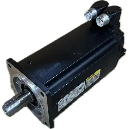
I. Overview
REXROTH MSK060C-0600-NN-M1-UP1-NSNN is a synchronous servo motor whose core function is to achieve precise three-loop closed-loop control of position, speed, and torque by cooperating with Rexroth servo drives (such as IndraDrive Cs/Ds series), converting electrical signals into stable and accurate mechanical motion. Adopting a permanent magnet synchronous structure, this motor features high torque density, fast dynamic response, and low inertia. Equipped with a multi-turn absolute encoder and a rotatable connection plug, it has a protection class of IP65 (typical value) and is compatible with industrial buses such as Profinet and EtherCAT. Widely used in scenarios requiring strict motion control accuracy and stability, such as CNC machine tools, industrial robots, precision assembly lines, packaging machinery, and automated conveying systems, it serves as a core power executive component in industrial precision motion control systems.
II. Key Features
Ultra-High Precision Motion Control
Equipped with a multi-turn absolute encoder with Hiperface interface, featuring a resolution of 131,072 steps/revolution (typical value). Combined with the drive's three-loop closed-loop control (position loop, speed loop, current loop), the positioning accuracy can reach ±0.001°, and the repeat positioning accuracy is ±0.0005°, meeting the position control requirements of ultra-precision equipment.
Supports electronic gear ratio and electronic cam functions. Motion curves can be flexibly configured through drive software, adapting to complex trajectory control scenarios (such as robot joint linkage, CNC machine tool circular interpolation).
High Dynamic and Power Performance
Rated stall torque of 8.8N·m, peak torque up to 24N·m, and rated speed of 6000rpm (the "0600" in the model corresponds to the speed code). The high torque density design ensures strong power output in a compact volume, enabling rapid response to acceleration/deceleration commands (acceleration time ≤0.1s from 0 to 6000rpm).
Optimized rotor inertia design (typical value 0.0008kg·m²) with a dynamic response frequency ≥1kHz, supporting high-frequency start/stop and forward/reverse switching. Suitable for equipment with extremely high dynamic performance requirements, such as industrial robots and high-speed sorters.
High Reliability and Stable Operation
Adopts high-performance neodymium-iron-boron permanent magnets and Class F insulated windings, with a heat resistance temperature of 155℃. The temperature rise during continuous operation is ≤60K (surface temperature ≤85℃ at an ambient temperature of 25℃), and the Mean Time Between Failures (MTBF) exceeds 15,000 hours.
Protection class IP65, featuring dustproof and water jet protection capabilities, allowing direct installation outside the equipment. It can adapt to harsh industrial environments such as machine tool cutting fluid splashing and dust. The natural cooling design has no fan wear, reducing maintenance requirements.
Flexible Integration and Adaptability
Equipped with a 240° rotatable connection plug, facilitating cable routing and equipment installation, and adapting to narrow space layouts. Adopts standard flange dimensions (60mm frame size), supporting horizontal/vertical installation with strong replaceability.
Compatible with the full range of Rexroth IndraDrive Cs/Ds servo drives, supporting mainstream industrial buses such as Profinet, EtherCAT, and Modbus. It can achieve real-time communication and synchronous control with PLCs and motion controllers, supporting multi-axis linkage functions.
Comprehensive Protection and Diagnostic Functions
Built-in functions such as over-temperature protection, over-current protection, overload protection, and encoder fault detection. The drive provides real-time feedback of motor operating status (temperature, current, speed, fault codes), facilitating quick troubleshooting.
Supports drive auto-tuning function, which automatically identifies motor parameters such as stator resistance, inductance, and inertia, optimizes control algorithms, ensures matching between the motor and drive, and improves system stability and control accuracy.

III. Technical Specifications
IV. Working Principle
As a permanent magnet synchronous servo motor, the core working logic of MSK060C-0600-NN-M1-UP1-NSNN is "Command Signal → Drive Processing → Winding Excitation → Electromagnetic Torque → Precise Motion + Feedback Closed-Loop", with the specific process as follows:
Command Reception and Processing
The controller (PLC/motion control card) sends position, speed, or torque commands to the servo drive via industrial bus or pulse signals. After receiving the commands, the drive generates three-phase sine wave drive signals combined with internal control algorithms.
Winding Excitation and Torque Generation
The drive inputs three-phase alternating current into the motor stator windings to generate a rotating magnetic field. The stator rotating magnetic field interacts with the permanent magnets on the rotor, generating electromagnetic torque based on the principle of electromagnetic induction, driving the rotor to rotate synchronously with the rotating magnetic field.
Three-Loop Closed-Loop Feedback Control
Position Loop: The encoder collects rotor position signals in real time, feeds them back to the drive to compare with the command position, and corrects position deviations through PID adjustment to ensure positioning accuracy.
Speed Loop: Calculates the actual speed based on the differential of the position signal, compares it with the command speed, adjusts the output torque, and stabilizes speed fluctuations (speed fluctuation rate ≤±0.1%).
Current Loop: Detects the three-phase stator current, controls the current amplitude and phase, optimizes torque output, and suppresses overload and current distortion.
Dynamic Optimization and Protection
The drive real-time monitors motor parameters such as temperature, current, and voltage. If abnormalities such as over-temperature, over-current, or overload are detected, it immediately cuts off the output or reduces the torque to protect the motor and equipment. At the same time, it dynamically adjusts control parameters through the auto-tuning algorithm to adapt to load changes and ensure operational stability.
V. Operation Guide
Installation Steps
Installation Environment
Select a dry and well-ventilated installation location, away from high-temperature heat sources (such as frequency converters, heaters) and strong electromagnetic interference sources. Avoid direct exposure of the motor to corrosive gases or severe vibration environments. The mounting surface must be flat and sturdy (flatness ≤0.1mm).
Mechanical Installation
Fix the motor flange to the equipment mounting base with M6 bolts (recommended torque: 8N·m), ensuring the flange end face is tightly fitted to the mounting surface without gaps (to avoid noise and precision loss caused by vibration).
When connecting the output shaft to the load (coupling/gear), the coaxiality error shall be ≤0.05mm and the end runout ≤0.03mm. Use an elastic coupling to absorb installation deviations. Do not strike the shaft end (to prevent damage to bearings and encoders).
For vertical installation, install a drip-proof device at the shaft end to prevent lubricating oil from seeping into the motor.
Wiring Specifications
Power Cable Wiring: Connect the U/V/W terminals of the drive to the corresponding terminals of the motor with a tightening torque of 2.5N·m to ensure firm wiring (avoid current imbalance caused by poor contact). Do not reverse the power polarity. Use 4mm² shielded cables for power cables, with the shield layer grounded at one end.
Encoder Wiring: Use Hiperface dedicated shielded cables to connect the motor encoder plug to the drive encoder interface. Ensure correct pin correspondence (refer to the drive manual wiring diagram) to avoid static damage to the encoder.
Cable Routing: Separate the power cables from the encoder cables (spacing ≥10cm) to avoid electromagnetic interference. The cable bending radius shall be ≥15 times the cable diameter to prevent internal wire breakage.
2. Drive Configuration and Debugging
Drive Selection and Matching
Core Parameter Configuration
Control Mode: Select position mode (pulse/bus command), speed mode (analog/bus command), or torque mode according to requirements.
Electronic Gear Ratio: Set the electronic gear ratio parameters according to the load transmission ratio (e.g., "Numerator = Transmission Ratio × Encoder Resolution, Denominator = Mechanical Displacement Unit") to achieve precise position mapping.
Gain Adjustment: The default position loop gain (P2-03) is 5.0, and the default speed loop gain (P3-05) is 10.0. If jitter occurs during low-speed operation, the gain can be appropriately reduced; if the high-speed response is insufficient, the gain can be slightly increased.
Auto-Tuning and Trial Operation
Start the drive auto-tuning function (P0-10=1). The drive automatically identifies motor parameters such as stator resistance, inductance, and inertia, and generates optimal control parameters. Restart the drive after auto-tuning is completed.
Low-Speed Trial Operation: Send a 100rpm speed command, observe whether the motor operates stably without abnormal noise; monitor current fluctuations through software (normal fluctuation ≤±0.5A).
Positioning Accuracy Test: Send a fixed position command (e.g., rotate 360°), check the deviation between the actual position and the command position (normal deviation ≤±0.001°). If the deviation is too large, re-calibrate the encoder zero point.
3. Operation and Maintenance
Status Monitoring
Regular Maintenance
Monthly: Clean dust and heat dissipation holes on the motor surface with compressed air; check whether the power cable and encoder cable plugs are loose.
Every 6 Months: Supplement bearing grease (the dosage is 1/3-1/2 of the internal bearing space, using grease with a heat resistance temperature above 150℃); check the tightness of the flange fixing bolts.
Annually: Measure the winding insulation resistance with a 500V megohmmeter (normal ≥1MΩ); detect the encoder accuracy (deviation ≤0.001°); replace aging seals.
Notes
Do not plug or unplug cables while the motor is running. Before maintenance, cut off the drive power supply and wait for 5 minutes (for discharge completion).
For long-term idleness (more than 3 months), power on and run the motor for 15 minutes every month to avoid bearing rust and permanent magnet demagnetization.
Overload operation is strictly prohibited (the load torque shall not exceed 1.1 times the rated torque), otherwise it will cause overheating damage to the windings.
4. Common Troubleshooting