Material
Other, Global universal model
Condition
Other, Global universal model
Task
Other, Global universal model
Mathematical Model
Other, Global universal model
Signal
Other, Global universal model
Customized
Non-Customized
Structure
Other, Global universal model
Operating Temperature
-25℃~45℃
Relative Humidity
5%-95% (non-condensing)
Dimensions
210mm × 80mm × 80mm
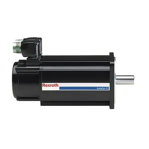
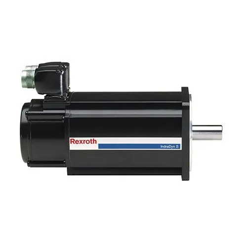
The REXROTH MSK050C-0600-NN-M1-UP1-NSNN is a compact permanent magnet synchronous servo motor. With a rated power of 6kW, high dynamic response, and modular design, it is widely used in scenarios such as feed axis drive of precision CNC machine tools, high-precision positioning of electronic manufacturing equipment, drive of robot end effectors, overprint control of printing and packaging equipment, and precision transmission of semiconductor packaging equipment. It undertakes key tasks including high-precision speed regulation, micron-level position control, and stable torque output.
Its core advantages lie in the adoption of next-generation permanent magnet synchronous technology and optimized mechanical structure design. While achieving high power density output, it can form a high-speed closed-loop control chain of "command issuance - power execution - status feedback" when matched with Rexroth IndraDrive series servo drives. It provides a power solution with precision, efficiency, and reliability for high-end precision manufacturing scenarios, and is a technologically mature high-performance servo motor product in the field of precision automation.
Technical Parameters
1.1 Core Electrical Parameters
Adopts a permanent magnet synchronous motor topology, with a rated power of 6kW, rated voltage of 380V AC (three-phase), rated current of 15.2A, and rated frequency of 100Hz.
Rated speed is 3000r/min, maximum speed is 6000r/min (short-time operation, duration ≤60s, duty cycle 10%), and speed accuracy is ≤±0.005% (at rated speed, when matched with a high-precision encoder).
Rated torque is 19.1N·m, peak torque is 57.3N·m (peak duration 3s), and torque ripple is ≤±0.5%.
Motor constant (Km) ≥3.0N·m/√kW, power factor ≥0.92 (under rated load), and efficiency class reaches IE4 (in accordance with GB 18613-2020 standard), with energy consumption reduced by approximately 15% compared to IE3 class.
1.2 Rotor and Feedback Parameters
The rotor uses high magnetic energy product neodymium-iron-boron (NdFeB) permanent magnets. The magnetic steel is installed via an embedded process, and has undergone 180℃ high-temperature curing and magnetic performance stability testing, which can effectively prevent magnetic steel from falling off and demagnetizing during high-speed operation.
Equipped with a high-precision incremental photoelectric encoder (UP1 feedback version) with a resolution of 1024 lines/revolution, supporting 4x frequency multiplication processing (up to 4096 pulses/revolution). A multi-turn absolute encoder (13-bit multi-turn + 16-bit single-turn) can be optionally configured to meet micron-level positioning requirements.
The encoder adopts differential signal transmission, with anti-interference capability complying with EN 61000-6-2 standard. It supports real-time interaction of position, speed, and status signals with the drive, enabling high-speed closed-loop control.
1.3 Structural and Installation Parameters
Adopts a compact structural design, with a frame size of 50C and an installation type of B5 (flange mounting). It is equipped with a standard M1-type installation interface and is compatible with B3 (foot mounting) adapter brackets.
The motor shaft diameter is 20mm, shaft extension length is 30mm, and it uses a single-key connection (key width 5mm). The shaft end runout accuracy is ≤0.01mm (ISO 1940-1 G4 class).
The motor length (including encoder) is 285mm, weight is 19kg, and power density reaches 0.316kW/kg.
The protection class is IP65 (motor body), and the encoder protection class is IP67. The shaft end adopts double sealing of double-lip skeleton oil seal + dust cover.
The cooling method is self-fan cooling (standard intelligent speed-regulating fan, speed adjustable from 0 to 5000r/min), and a water-cooling kit can be optionally configured to achieve forced cooling (for high-temperature environments).
1.4 Environmental Adaptability Parameters
The operating temperature range is -25℃~45℃ (derating is required when the ambient temperature exceeds 45℃, with a derating of 1.5% for each 1℃ increase), and the storage temperature range is -40℃~85℃.
The relative humidity is 5%~95% (no condensation, when temperature ≤40℃), which can cope with various environments such as clean rooms and humid workshops.
The vibration resistance performance complies with IEC 60068-2-6 standard (10~2000Hz, acceleration 8g), and the impact resistance performance complies with IEC 60068-2-27 standard (15g, 11ms half-sine wave).
The insulation class is Class H, the winding temperature resistance is 180℃, the insulation resistance is ≥200MΩ (500V DC, at room temperature), and the voltage resistance is 2500V AC/1min (between winding and housing).
1.5 Compatibility and Reliability Parameters
Perfectly compatible with Rexroth IndraDrive M series servo drives (such as HCS02.1E-W0070-A-03-NNNN, HCS03.1E-W0150-A-03-NNNN). Data communication is realized through the DRIVE-CLiQ high-speed interface, with a communication rate of 100Mbps, supporting automatic motor parameter identification.
Supports mainstream industrial Ethernet protocols such as PROFINET, EtherCAT, and Modbus-TCP (drive adaptation required).
Mean Time Between Failures (MTBF) ≥350,000 hours, and bearing life ≥25,000 hours (under rated speed and long-term lubrication conditions).
Built-in PTC thermistor (activated at 150℃), speed monitoring, and overload protection functions. Fault signals can be uploaded to the control system in real time through the drive.
Functional Features
2.1 Ultra-Compact with High Power Density for Space Saving
Adopts optimized electromagnetic topology and compact mechanical structure design, achieving a rated power output of 6kW within the 50C frame size, with a power density of 0.316kW/kg. Compared with traditional servo motors of the same power class, its volume is reduced by 25% and weight by 20%.
The motor length is only 285mm (including encoder), and with the B5 flange mounting type, it can be adapted to narrow installation spaces such as CNC machine tool feed axes and robot joints.
The lightweight design (19kg) reduces the inertia at the load end, providing a foundation for high dynamic response of the system.
2.2 Micron-Level Control Precision for High-End Scenarios
Equipped with a high-precision incremental encoder (1024 lines/revolution, supporting 4x frequency multiplication), and matched with the drive's vector control algorithm, it achieves a speed accuracy of ≤±0.005% and a position control accuracy of ≤±0.002mm (when matched with precision ball screw transmission), which can meet micron-level positioning requirements such as semiconductor packaging and electronic chip testing.
The rotor has a low moment of inertia of 0.032kg·m², with excellent acceleration and deceleration performance. The acceleration time from 0 to 3000r/min is ≤0.15s, and the dynamic response frequency is ≥600Hz, which can quickly follow command changes and reduce dynamic errors.
2.3 Wide-Range Speed Regulation and Stable Torque Output
Supports a wide speed regulation ratio of 1:1500 (2r/min~3000r/min), with excellent torque stability during low-speed operation (torque ripple ≤±1% at 2r/min), which can adapt to multi-condition switching needs such as low-speed feeding and high-speed overprinting of printing and packaging equipment, and low-speed cutting and high-speed feeding of CNC machine tools.
The peak torque reaches 57.3N·m (3 times the rated torque), which can cope with short-term heavy-load scenarios (such as emergency acceleration of CNC machine tools and heavy object grabbing by robots) without the need to configure a motor with redundant power, reducing equipment costs.
It can output 100% rated torque at zero speed, and achieve precise positioning and locking when matched with an optional electromagnetic brake.
2.4 Enhanced Reliability Design for Complex Working Conditions
The motor windings use Class H insulation materials and undergo vacuum pressure impregnation (VPI) process treatment, with excellent insulation performance, enabling long-term stable operation in high-temperature and high-humidity environments.
The rotor magnetic steel adopts embedded installation + anti-demagnetization coating treatment, and has passed 200℃ high-temperature aging testing. The magnetic performance attenuation rate is ≤5% (within 10 years of service life) under overload or extreme temperature conditions.
The IP65 protection class combined with the double-sealing design at the shaft end can effectively isolate impurities such as dust and cutting fluid, making it suitable for multi-pollution scenarios such as machine tool processing and food packaging.
The bearings use Schaeffler high-precision bearings, filled with long-acting synthetic lubricating grease, reducing maintenance frequency.
2.5 Modular Adaptation and Intelligent Maintenance for Reduced Integration Costs
Adopts a standardized installation interface (M1-type flange), which can directly replace motors of other brands with the same specification without modifying the equipment installation structure.
Supports plug-and-play with Rexroth IndraDrive series drives, automatically reading motor parameters through the DRIVE-CLiQ interface, eliminating the need for manual configuration and shortening the integration cycle.
Built-in intelligent monitoring components can feed back motor temperature, speed, operating status and other data in real time. The drive can realize fault alarm and protection for overload, over-temperature, over-voltage, etc. With the status indicator window, maintenance personnel can quickly locate faults and reduce maintenance costs.

Working Principle
3.1 Command Receiving and Drive Signal Generation
The upper controller (such as CNC, PLC) sends speed, position, or torque commands to the Rexroth IndraDrive drive. The drive reads the inherent motor parameters (such as rated power, number of pole pairs) through the DRIVE-CLiQ interface, and generates three-phase sine wave drive current after processing by the vector control algorithm.
At the same time, the drive receives the motor feedback signal in real time through the encoder interface, laying the foundation for closed-loop control.
3.2 Magnetic Field Interaction and Power Output
The three-phase current output by the drive is applied to the motor stator windings, generating a rotating magnetic field (synchronous speed n=60f/p, where f is the current frequency and p is the number of pole pairs).
The rotor permanent magnets generate a constant magnetic field. The stator rotating magnetic field interacts with the rotor magnetic field to generate electromagnetic torque, driving the rotor to rotate synchronously.
By adjusting the frequency (to regulate speed) and amplitude (to regulate torque) of the drive current, precise control of the motor speed and torque is achieved.
During position control, the drive dynamically adjusts the phase of the rotating magnetic field according to the deviation between the command position and the encoder feedback position, ensuring the rotor accurately reaches the target position.
3.3 Status Feedback and Closed-Loop Regulation
The encoder collects the rotor position and speed signals in real time and transmits them to the drive through differential signals. The drive calculates the deviation between the command and the feedback, and dynamically optimizes the phase and amplitude of the output current to realize closed-loop regulation of speed, position, or torque.
The built-in PTC thermistor monitors the winding temperature in real time. When the temperature exceeds 150℃, it sends an over-temperature signal to the drive, which immediately cuts off the output and alarms to protect the motor from overheating damage.
The intelligent fan automatically adjusts its speed according to the motor temperature (running at low speed below 30℃ and high speed above 60℃), balancing heat dissipation and energy consumption.
3.4 Auxiliary Function Support
The standard self-fan cooling system realizes on-demand heat dissipation through intelligent temperature control, reducing operating noise and energy consumption.
The optional electromagnetic brake device is energized to brake when the motor stops, preventing the rotor from sliding and ensuring positioning accuracy.
The modular interface design supports encoder upgrades (such as replacing with an absolute encoder) and cooling method upgrades (from self-fan cooling to water cooling), improving equipment expandability.
Common Faults and Solutions
4.1 Fault 1: Motor Fails to Start, Drive Reports "Motor Communication Fault"
Possible Causes
Solutions
Check the connectors at both ends of the DRIVE-CLiQ cable, re-plug and fasten them, and confirm the cable is not damaged.
Re-execute the "motor identification" process through the IndraWorks engineering software to ensure the drive reads the complete motor parameters.
Replace with a DRIVE-CLiQ cable of the same model for testing to rule out cable faults.
Connect the motor to a normal drive. If the fault is still reported, the motor encoder or communication interface is faulty, and the motor needs to be returned to the factory for repair.
4.2 Fault 2: Decreased Operating Precision, Excessive Position Deviation
Possible Causes
Encoder signal interference.
Excessive coaxiality deviation between the motor and the load.
Unoptimized drive parameters.
Wear of mechanical transmission components (such as lead screw backlash).
Solutions
Check if the encoder cable is a shielded twisted pair, whether the shield layer is single-ended grounded (grounding resistance ≤4Ω), and ensure the distance from the power cable is ≥30cm.
Use a dial indicator to detect the coaxiality between the motor and the load. The radial runout should be ≤0.03mm and the end runout ≤0.02mm. Adjust the installation position if the deviation exceeds the standard.
Optimize the position loop and speed loop parameters (such as increasing the position loop gain) through the drive software.
Check the mechanical transmission components and replace worn parts such as lead screws and couplings.
4.3 Fault 3: Abnormal Noise and Vibration During Operation
Possible Causes
Misalignment between the motor and the load.
Bearing wear or lubrication failure.
Poor dynamic balance of the rotor.
Load jamming.
Solutions
Re-calibrate the coaxiality between the motor and the load to meet the installation standards.
Remove the motor end cover, check if the bearings are worn or the grease is dried up, replace the bearings and add special lubricating grease.
Conduct a dynamic balance test on the motor rotor. The unbalance should be ≤G1.0 class (ISO 1940-1). If the deviation exceeds the standard, return the rotor to the factory for correction.
Disconnect the connection between the motor and the load, manually rotate the load shaft, and troubleshoot load jamming faults (such as reducer jamming, poor guide rail lubrication).
4.4 Fault 4: Drive Reports "Motor Over-Temperature" Fault
Possible Causes
Long-term overload operation of the motor.
Faulty cooling fan or blocked air duct.
Excessively high ambient temperature.
PTC thermistor fault.
Solutions
Monitor the real-time motor torque through the drive software. If it exceeds the rated value for a long time, evaluate the load matching and replace with a higher-power motor if necessary.
Check if the cooling fan is running, clean the dust on the motor surface and air duct, and replace the fan if it is faulty.
When the ambient temperature exceeds 45℃, install an additional cooling fan or water-cooling kit, and implement derating at the same time.
Measure the resistance value of the PTC thermistor. It should be approximately 1kΩ at room temperature and 10kΩ at 150℃. Replace the thermistor if the resistance is abnormal.
4.5 Fault 5: Encoder Fault Alarm, Closed-Loop Control Failure
Possible Causes
Loose or broken encoder cable.
Internal encoder damage (code disc contamination/wear).
Drive encoder interface fault.
Unstable power supply voltage.
Solutions
Re-fasten the encoder cable connectors, check the cable integrity, and replace the damaged cable.
Remove the encoder end cover, clean the oil and dust on the code disc surface. Replace the encoder if the code disc is worn.
Connect a normal encoder to the faulty drive. If the alarm is still triggered, the drive interface is faulty and needs to be repaired.
Measure the encoder power supply voltage (DC 5V±0.1V). If the voltage is unstable, troubleshoot the drive power supply circuit.









 Contact Platform Support
 Help Center