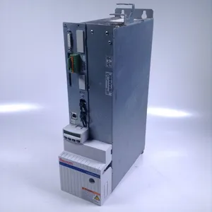
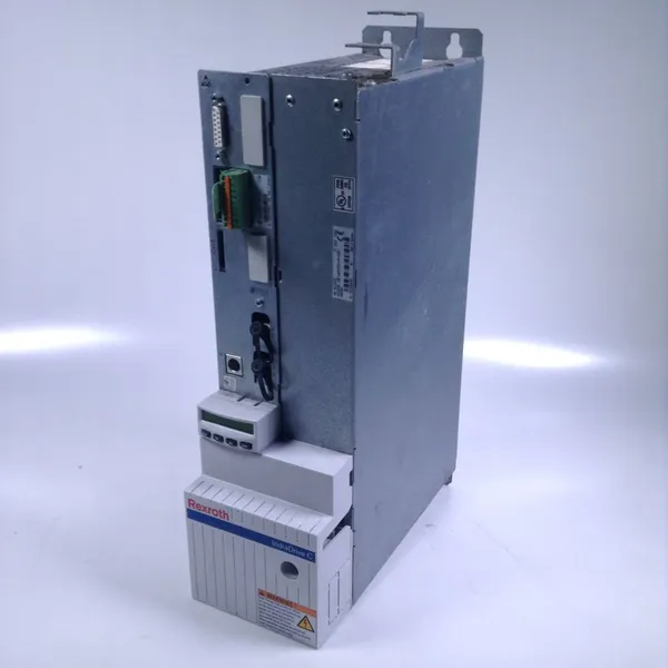
The REXROTH CSB01.1N-AN-ENS-NNN-NN-S-NN-FW is a compact servo controller belonging to the CSB series. As the core control unit of medium and low-power servo control systems, it is mainly used in precision motion control scenarios such as machine tools, electronic manufacturing equipment, packaging machinery, printing machinery, and automated production lines. It undertakes core tasks including speed control, position control, torque control, and dynamic response adjustment of servo motors.
Its core function is to achieve closed-loop control by receiving control commands from upper-level controllers (such as PLC and CNC) and combining them with motor feedback signals (encoder signals), thereby accurately adjusting the operating status of servo motors. Meanwhile, it is equipped with comprehensive fault diagnosis, safety protection, and communication interaction capabilities to ensure high-precision and high-dynamic motion control of equipment.
With its compact design, flexible control modes, and strong adaptability, this controller has become the preferred equipment for medium and low-power precision motion control scenarios, providing core support for the efficient operation and precise control of equipment.
I. Technical Parameters
1. Power and Motor Adaptation Parameters
It is compatible with three-phase asynchronous servo motors or permanent magnet synchronous servo motors, with a rated output power range of 0.75kW to 2.2kW (depending on specific configurations). The rated output current is 6A (continuous) and 18A (peak, with a duration of 3s). The input power supply is three-phase AC 380V-480V (±10%), and the power frequency is 50Hz/60Hz. It is equipped with a power supply soft-start function to suppress inrush current during power-on. It supports the motor parameter self-tuning function, which can automatically identify the motor model and match the optimal control parameters. It is compatible with the full range of Rexroth medium and low-power servo motors, and also works with third-party standard servo motors.
2. Control Performance Parameters
The control modes support three basic modes: position control, speed control, and torque control, and quick switching between modes can be realized via commands. The position control accuracy depends on the encoder resolution; it is compatible with incremental encoders (supporting up to 1024 lines) and absolute encoders (supporting up to 17 bits), with a positioning accuracy of ≤±0.001mm (when used with ball screw transmission). The speed control range is 0-3000rpm (for asynchronous motors) and 0-6000rpm (for synchronous motors), with a speed fluctuation of ≤±0.1rpm (at rated speed). The torque control accuracy is ≤±5% of the rated torque. The dynamic response time is ≤1ms (for speed step response), enabling quick following of load changes.
3. Feedback and Communication Parameters
It is standard-equipped with incremental encoder interfaces (TTL/HTL) and optionally with absolute encoder interfaces (PROFIBUS/SSI). It supports data reading from multi-turn absolute encoders to achieve power-off position memory function. The communication interfaces are standard-equipped with two industrial Ethernet interfaces: EtherNet/IP and PROFINET, and are compatible with bus protocols such as Modbus-RTU and CANopen, allowing direct access to mainstream industrial automation networks. The maximum communication rate is 100Mbps, and the command response delay is ≤0.2ms, ensuring real-time transmission and execution of upper-level commands.
4. Safety and Environmental Parameters
It is equipped with comprehensive protection functions, including overcurrent protection, overvoltage protection, undervoltage protection, overtemperature protection, motor stall protection, encoder fault protection, and ground fault protection, with a fault response time of ≤100μs. Its safety level complies with the IEC 61508 SIL 2 standard, and it supports the Safe Torque Off (STO) function. The operating temperature range is 0℃-40℃ (without cooling fan) and 0℃-55℃ (with cooling fan). The storage temperature range is -20℃-60℃. The relative humidity range is 5%-95% (non-condensing). The protection level is IP20 (panel-mounted). Its overall dimensions are 140mm×180mm×100mm (width×height×depth), and it adopts rail-mounted installation, saving space in the control cabinet.
II. Functional Features
1. Multi-Mode Precise Control for Diverse Scenarios
It integrates three core control modes: position control, speed control, and torque control. Position control supports multiple methods such as jogging, continuous operation, and interpolation motion, enabling complex trajectory control (e.g., linear interpolation and circular interpolation, which requires collaboration with upper-level CNC). Speed control supports constant-speed operation and speed ramp adjustment, meeting the speed regulation needs of loads like fans and pumps. Torque control can achieve constant torque output, suitable for scenarios such as material winding and pressure control. The three modes can be quickly switched via upper-level commands or panel operations to meet the control requirements of multiple processes of equipment.
2. Compact Design + Flexible Adaptation for Reduced Integration Costs
Adopting a highly integrated circuit design, it is more than 30% smaller in size compared with traditional servo controllers. With a width of 140mm, it can be easily installed on a standard 35mm DIN rail, significantly saving installation space in the control cabinet. It supports "plug-and-play" with Rexroth servo motors, and can quickly complete configuration through the automatic parameter self-tuning function, reducing debugging time. It is compatible with third-party motors; precise control can be achieved by manually inputting motor parameters, reducing the difficulty of spare part selection. It supports independent single-axis control, and the number of axes can be flexibly expanded according to equipment requirements.
3. High Dynamic Response + Stable Operation for Guaranteed Control Accuracy
It adopts Bosch Rexroth's patented PID + feedforward control algorithm, combined with a high-speed signal processing unit, with a dynamic response time of ≤1ms, which can quickly suppress speed or position deviations caused by load fluctuations. It is equipped with a load observer function that can real-time predict load changes and adjust the output in advance, improving the anti-interference ability of the system. The encoder signal acquisition frequency is up to 1MHz, ensuring accurate acquisition of position and speed signals and providing reliable data support for closed-loop control. Under rated load, the speed fluctuation is controlled within ±0.1rpm, and the positioning accuracy can reach the micron level, meeting the requirements of high-precision scenarios such as electronic manufacturing and precision machining.
4. Comprehensive Protection + Intelligent Operation and Maintenance for Reduced Downtime Risks
It has built-in more than 12 fault protection functions. When abnormalities such as overcurrent, overtemperature, and encoder faults are detected, it immediately cuts off the output, triggers an alarm, and records the fault code and operating parameters at the time of the fault. It is optionally equipped with a 7-inch color touch panel, which can intuitively display operating parameters and fault information, and support parameter setting and fault reset. It supports remote monitoring of the controller's operating status, reading of fault records, and modification of control parameters through the upper-level system, enabling remote operation and maintenance. It has a parameter backup and restoration function, which can quickly copy configuration parameters to devices of the same model, improving the efficiency of batch debugging.

III. Working Principle
1. Command Receiving and Mode Selection Stage
The controller receives control commands from upper-level controllers (PLC/CNC) via industrial Ethernet interfaces (such as PROFINET). These commands include control mode commands (position/speed/torque), target parameters (target position/target speed/target torque), and operation commands (start/stop/emergency stop). The internal logic unit of the controller selects the corresponding control mode according to the commands and invokes preset control parameters (such as PID parameters, acceleration time, and deceleration time).
2. Feedback Signal Acquisition Stage
When the servo motor is running, the encoder real-time collects the motor's speed and position signals and transmits them to the controller's signal processing unit via the encoder interface. The signal processing unit decodes and filters the encoder signals, converts analog signals into digital signals, calculates the motor's current actual speed, actual position, or actual torque, and transmits them to the control algorithm unit.
3. Closed-Loop Regulation and Calculation Stage
The control algorithm unit compares the target parameters of the upper-level commands with the actual parameters collected by the encoder, and calculates the deviation values (such as position deviation, speed deviation, and torque deviation). It uses the PID + feedforward control algorithm to calculate the deviation values, and combines with the load change information fed back by the load observer to calculate the voltage and current regulation signals that need to be output. In the case of position control mode, it also combines with the motion trajectory planning algorithm to generate a smooth speed curve, avoiding impact during startup and shutdown.
4. Power Output and Fault Protection Stage
The regulation signals are transmitted to the power amplification unit. The power amplification unit rectifies the three-phase input AC into DC, and then inverts the DC into three-phase AC with adjustable frequency and voltage via the IGBT inverter. This AC is output to the stator windings of the servo motor to drive the motor to operate according to the adjusted parameters. At the same time, the protection unit real-time monitors parameters such as input voltage, output current, controller temperature, and motor speed. When it detects that a parameter exceeds the safe range (e.g., the output current exceeds 1.5 times the rated value), it immediately cuts off the power output, triggers an alarm, and uploads fault information to ensure equipment safety.
IV. Common Faults and Solutions
Fault 1: Communication Interruption, Unable to Receive Upper-Level Commands
Possible Causes
Broken or poor contact of Ethernet cables;
Loose or damaged communication interfaces;
Incorrect configuration of communication parameters (such as IP address, port number, and bus protocol);
Faulty communication module of the upper-level controller;
Signal loss caused by electromagnetic interference.
Solutions
Check the continuity of the Ethernet cable, use a cable tester to verify the integrity of the cable, and replace damaged cables;
Reconnect the communication interface connectors to ensure tight contact; if the interface is loose, fasten or replace it;
Verify that the communication parameters (IP address, subnet mask, gateway, and bus protocol) of the controller and the upper-level system are consistent;
Connect the controller to a backup upper-level system for testing; if communication is restored, the original upper-level controller is faulty, and the upper-level module needs to be repaired;
Add a shielding layer to the communication cable and ground it at one end, keep it away from strong interference sources such as inverters and high-power motors, and install a signal isolator if necessary.
2. Fault 2: Unstable Operation After Motor Startup, Large Fluctuations in Speed/Position
Possible Causes
Incomplete motor parameter self-tuning or incorrect parameters;
Unreasonable PID parameter configuration;
Interference to encoder signals or loose encoder installation;
Excessive load fluctuations;
Unstable power supply voltage.
Solutions
Execute the motor parameter self-tuning function to ensure the controller correctly identifies the motor parameters; if self-tuning fails, manually input the motor nameplate parameters;
Access the controller's parameter interface, adjust the PID parameters (proportional coefficient, integral time, and derivative time), and optimize the parameters through the trial-and-error method to reduce fluctuations;
Check whether the encoder is firmly installed and whether the cable shielding is in good condition; re-fasten the encoder and organize the cables to avoid parallel routing with power cables;
Check whether the load has problems such as jamming and sudden changes, and eliminate load faults; if load fluctuations are unavoidable, enable the load observer function;
Use a multimeter to detect the input power voltage, ensure it is within the range of 380V-480V±10%; if the voltage fluctuates greatly, install a voltage stabilizer.
3. Fault 3: Controller Reports "Overcurrent Fault", Unable to Start the Motor
Possible Causes
Short circuit or grounding of the motor winding;
Damaged IGBT in the power amplification unit;
Motor stall (load jamming);
Misjudgment caused by encoder faults;
Excessive starting current (too short acceleration time setting).
Solutions
Disconnect the connection between the motor and the controller, use a megohmmeter to detect the insulation resistance of the motor winding; if it is ≤0.5MΩ, the winding is short-circuited or grounded, and the motor needs to be repaired;
Replace with a backup controller for testing; if the fault disappears, the power amplification unit of the original controller is damaged, and it needs to be returned to the factory for repair;
Manually rotate the motor shaft to confirm there is no jamming; if jamming occurs, troubleshoot load faults (such as mechanical jamming);
Check whether the encoder signal is normal, use an oscilloscope to observe the encoder output waveform; replace the encoder if it is abnormal;
Access the controller's parameter interface, extend the acceleration time parameter to reduce the peak starting current.
4. Fault 4: Controller Reports "Encoder Fault", Unable to Control Normally
Possible Causes
Broken encoder cable;
Faulty encoder power supply;
Loose or misaligned connection between the encoder and the motor shaft;
Internal damage to the encoder;
Faulty encoder interface of the controller.
Solutions
Check the continuity of the encoder cable, focus on checking whether the connector is broken, and replace damaged cables;
Detect the encoder power supply (usually 5V DC) to ensure stable voltage; if the power supply is faulty, repair the power supply module;
Remove the encoder, check whether its connection to the motor shaft is firm and whether the coupling is misaligned, then reinstall and calibrate it;
Replace with a backup encoder for testing; if the fault disappears, the original encoder is damaged;
Connect the backup encoder to the original controller; if the fault still occurs, the encoder interface of the controller is damaged, and it needs to be returned to the factory for repair.









 Contact Platform Support
 Help Center