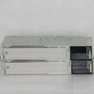
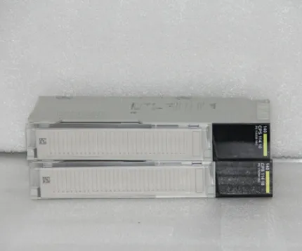
I. Overview
Schneider 140CPS11410 is a core power supply module for the Modicon Quantum series of Programmable Logic Controllers (PLCs). Its core positioning is a "high-reliability power supply unit for medium and large-sized industrial control systems", focusing on solving the stable power supply problem of main controllers and various I/O modules in complex industrial scenarios such as metallurgy, chemical engineering, electric power, and intelligent manufacturing, thereby providing power support for the reliable operation of the entire control system.
This module is highly compatible with the backplane architecture of Modicon Quantum series PLCs. It adopts an industrial-grade switching power supply topology, redundant power supply design, and multiple protection technologies. Its key functions include converting industrial-grade AC or DC input power into stable DC power required by controllers and I/O modules, as well as implementing critical tasks such as power status monitoring, fault early warning, and redundant switching. This ensures the continuity, stability, and safety of power supply for the control system in harsh industrial environments.
As a main power supply module in the Modicon Quantum series, the 140CPS11410 has core advantages such as a wide input voltage range, high output stability, dual-channel redundant output, and industrial-grade protection performance. It can adapt to grid voltages in different regions without additional power conditioning equipment, effectively improving the power supply adaptability and reliability of the system.
It is widely used in various medium and large-sized industrial automation control systems, such as blast furnace control systems in the metallurgical industry, closed-loop control systems for reactors in the chemical industry, auxiliary control systems for generator sets in the electric power industry, and large-scale production line control platforms in the intelligent manufacturing field. The module features seamless compatibility with the Modicon Quantum system, wide-range input adaptation, stable dual-channel output, multiple fault protections, and real-time status monitoring. It can adapt to harsh industrial environments such as high temperature, high humidity, and strong electromagnetic interference, fully meeting the high requirements of medium and large-sized industrial control systems for power supply accuracy, reliability, and safety.
II. Technical Specifications

III. Functional Features
1. Deep Compatibility with Modicon Quantum System for Efficient and Reliable Deployment
It adopts a hardware adaptation architecture specially developed for the Modicon Quantum series, achieving full-dimensional deep compatibility with the system backplane, main controller, and various I/O modules, significantly improving deployment efficiency and operational stability.
The module can be directly inserted into the dedicated power supply slot of the Quantum series standard backplane, and mechanical fixation and electrical connection with the backplane are realized through the gold fingers at the bottom, without additional wiring or adaptation devices. Physical installation only requires two steps: insertion and fixation, and input power wiring, reducing installation time by 60% compared with traditional power supply modules.
After being connected to the system, the main controller can automatically identify the module model, output parameters, and working status through the backplane bus, eliminating the need for engineers to manually configure device information. Key parameters such as input voltage, output current, and temperature of the power supply module can be directly monitored in the Unity Pro software, simplifying the system management process.
It supports collaborative operation with the Quantum series redundant system, enabling hot backup of dual power supply modules. Combined with the system redundant logic, it ensures "zero interruption" of the power supply system, making it particularly suitable for critical industrial control scenarios such as chemical engineering and electric power.
2. Wide-Range Input Adaptation for Worry-Free Global Application
With a wide-range input power supply design, it can flexibly adapt to power supply requirements in different regions and scenarios, enabling global deployment without module replacement, and greatly improving the versatility and applicability of the module.
The module supports a wide AC input range of 100-240V AC by default, and can automatically adapt to 50Hz or 60Hz grid frequencies. It can be directly connected to either the domestic 220V AC standard grid or the overseas 110V AC grid without additional transformers.
At the same time, it supports a customized DC input version of 110-300V DC, which can adapt to DC bus power supply scenarios in industrial fields, such as new energy power stations and rail transit control systems.
The input circuit adopts wide-band filtering technology and surge suppression circuit, which can effectively resist grid voltage fluctuations, harmonic interference, and instantaneous surge impacts. When the input voltage fluctuates within ±10%, the output voltage fluctuation is still ≤±0.5%, ensuring stable power supply even in industrial scenarios with poor grid quality.
The input interface is equipped with reverse connection protection, which can effectively prevent module damage caused by wrong wiring and improve the safety of installation and commissioning.
3. Stable Dual-Channel Output to Meet Diverse Power Supply Needs
It adopts a dual-channel independent output design of 5V DC and 24V DC, which respectively meets the power supply needs of the Quantum system backplane and external I/O devices, realizing precise allocation and efficient utilization of power supply resources.
The 5V DC main output provides power for the system core, with a maximum output current of 20A, which can meet the simultaneous power supply needs of the main controller, multiple I/O modules, and expansion modules. The output voltage accuracy is ±0.5% and the ripple is ≤50mVpp, ensuring stable and reliable controller operation and bus communication.
The 24V DC auxiliary output supplies power to external devices, with a maximum output current of 5A. It can directly provide power for external devices such as sensors, actuators, and indicator lights, without the need for additional independent power supply modules, simplifying the system power supply architecture.
The dual-channel outputs adopt independent voltage stabilization circuits and protection mechanisms. When one channel of output encounters faults such as overload or short circuit, the other channel of output is not affected, ensuring the independence and safety of power supply for the core system and external devices.
The module is equipped with dual-channel output voltage fine-tuning potentiometers, allowing engineers to fine-tune the output voltage within a range of ±5% according to actual needs to adapt to the power supply requirements of special devices.
4. Multiple Protection Mechanisms for Secure Power Supply
It integrates multiple protection functions for the entire input and output links, which can comprehensively resist various power supply fault risks, prevent module damage and downstream device damage, and significantly improve the safety of the power supply system.
The input side is equipped with over-voltage, under-voltage protection, and surge protection. When the input voltage exceeds the range of 100-240V AC or encounters an instantaneous surge impact, the module will quickly cut off the input circuit or suppress the surge current to avoid high-voltage impact on the internal circuit.
For the output side, over-voltage, over-current, and short-circuit protections are separately designed for the 5V and 24V outputs. When the output voltage exceeds 110% of the rated value, the output current exceeds 120% of the rated value, or a short circuit occurs, the protection circuit will be triggered within 10μs. It protects the module and downstream devices through current limiting and current cutting. After the short-circuit fault is eliminated, the output can be automatically restored without manual intervention.
The module is equipped with an over-temperature protection function inside. When the module temperature is ≥70℃, the cooling fan starts automatically; when the temperature is ≥80℃, over-temperature protection is triggered, cutting off part of the non-core outputs until the temperature drops to a safe range and returns to normal, avoiding module aging or damage caused by high temperature.
5. Intelligent Heat Dissipation Design for Adaptation to Harsh Environments
It adopts a composite heat dissipation design of "natural heat dissipation + intelligent fan heat dissipation", which has excellent heat dissipation performance, can operate stably in high-temperature industrial environments, and extend the service life of the module.
The module housing is made of cold-rolled steel plate, and the interior is designed with dense heat sinks. Natural convection can meet the heat dissipation needs under medium and low load (≤50%) conditions. Operation without a fan can reduce noise pollution, making it suitable for noise-sensitive scenarios.
When the module load is ≥50% or the internal temperature is ≥50℃, the built-in cooling fan starts automatically. The fan speed can be adjusted automatically according to the temperature—the higher the temperature, the faster the speed—ensuring a balance between heat dissipation efficiency and energy consumption.
The cooling fan adopts industrial-grade silent bearings, with a service life of ≥50,000 hours, and is equipped with a fault detection function. When the fan fails, a signal is output through the fault alarm dry contact to remind engineers to replace it in time.
The module's operating temperature range covers 0℃-60℃. Combined with efficient heat dissipation design, it can operate stably in high-temperature environments such as metallurgical workshops and steel plants without additional heat dissipation equipment.
6. Full-Dimensional Status Monitoring for Significantly Improved O&M Efficiency
It integrates full-dimensional status monitoring functions at the module level, input level, and output level, which can feedback power supply operation status in real time and quickly locate faults, significantly reducing O&M costs.
The module is equipped with 4 intuitive status indicators, and the working status is fed back through the on/off status of the indicators: the PWR light is always on when the input power is normal, and off when there is an input fault; the 5V OK light is always on when the 5V output is normal, and flashes when the output is abnormal; the 24V OK light is always on when the 24V output is normal, and flashes when the output is abnormal; the ALM light is always on when the module has a fault, and flashes for early warning.
The module transmits detailed status information (including input voltage, 5V/24V output voltage, output current, module temperature, fault type, etc.) to the main controller through the backplane bus. Engineers can view various parameters and historical operation data in real time through the Unity Pro software, which supports fault log storage (capable of storing 100 fault records) and export analysis.
When a power supply fault occurs, the fault alarm dry contact triggers an audible and visual alarm, and the software pops up a window to prompt the fault details. There is no need for engineers to check each module one by one, reducing fault location time by more than 80%.
IV. Common Faults and Solutions









 Contact Platform Support
 Help Center