

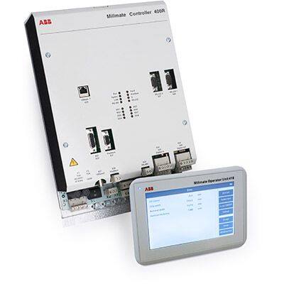
ABB 3BSE024388R3 PFXA401F Millmate Controller 400

Related Products
-
 ABB CI615K01 3BSE000756R1 Bus Extension KitNegotiableMOQ: 1 Piece
 -
ABB CI630K02 3BSE011002R1 AF100 Interface Kit to RedundanNegotiableMOQ: 1 Piece
-
ABB DC375a GJR2304400R1 Controller ModuleNegotiableMOQ: 1 Piece
-
ABB CT370a GJR2237500R1 Controller ModuleNegotiableMOQ: 1 Piece
-
ABB REM543CM214AAAB Machine TerminalNegotiableMOQ: 1 Piece
I. Overview
The ABB 3BSE024388R3 PFXA401F is a high-performance compact controller module, serving as a core component of the AC 800M series Distributed Control System (DCS). Specifically designed for medium-to-large industrial process control scenarios, this module focuses on meeting the precise control requirements of process industries. It undertakes key tasks such as control logic calculation, real-time on-site signal processing, cross-module data interaction, and communication with upper-level systems, acting as a core hub connecting on-site equipment and the control system.
With its modular design and high compatibility, the PFXA401F can be seamlessly integrated into the AC 800M control system architecture. It is suitable for harsh operating environments across multiple industries, including power generation, petrochemicals, metallurgy, water treatment, and papermaking. Not only does it possess efficient computing capabilities and a rich interface configuration, but it also ensures operational stability through comprehensive redundancy design and self-diagnostic mechanisms. This provides solid technical support for the continuity and automation of industrial production, effectively reducing the risk of equipment downtime and operational maintenance costs.
II. Technical Specifications
III. Functional Features
1. Efficient and Precise Control Capability
2. Multi-Protocol Compatibility and Redundant Communication
3. Comprehensive Self-Diagnosis and Fault Early Warning
4. Adaptability to Harsh Environments and Redundancy Guarantee
5. Convenient Configuration and Operation & Maintenance Management
IV. Common Faults and Solutions

Send Inquiry to This Supplier


You May Also Like
-
ABB REM545BM223AAAA Machine TerminalNegotiableMOQ: 1 Piece
-
ABB REM543CM216AAAA Machine TerminalNegotiableMOQ: 1 Piece
-
ABB 3BHB003431R0101 KUC720AE01 Power Control Drive BoardNegotiableMOQ: 1 Piece
-
ABB 3BHB000582P201 Multifunction Controller ModuleNegotiableMOQ: 1 Piece
-
ABB GVC707AE01 3BHB003149P104 Thyristor ModuleNegotiableMOQ: 1 Piece
-
ABB 3BHB038130R4004 DriveMonitor Version 4000 RBOX316NegotiableMOQ: 1 Piece
-
ABB GJR2366500R1010 Programmable Processing DeviceNegotiableMOQ: 1 Piece
-
ABB HESG447427R0001 70EI05A-E Input ModuleNegotiableMOQ: 1 Piece
-
ABB HESG447271R0002 70BK03B-ES Interface to Local BusNegotiableMOQ: 1 Piece
-
ABB DSQC656 3HAC025465-001 Robot Controller MainNegotiableMOQ: 1 Piece


