I. Overview
The ABB AX521 1SAP250100R0001 is a DC speed control controller and serves as the core control unit of the ABB DCS800 series DC speed control system. Its core positioning is to act as the "intelligent core" for DC motor drive control, focusing on high-precision closed-loop control of key operating parameters of DC motors such as speed, torque, and current. Through advanced vector control algorithms, wide-range adaptability, and enhanced protection mechanisms, it achieves smooth startup, precise speed regulation, and efficient operation of DC motors. It provides reliable control solutions for core industrial scenarios that rely on DC motor drives, including metallurgical steel rolling, mine hoisting, papermaking traction, and port lifting.
The application scenarios of this controller cover multiple industrial fields in depth:
In the metallurgical and steel industry, it can be used for speed control of the DC main drive motor of rolling mills, realizing precise adjustment of roll speed to ensure the uniformity of steel plate thickness.
In the mining industry, it is adapted to the DC motor of mine hoists. Through stable torque control, it ensures smooth startup/shutdown of the hoist and precise load adjustment, guaranteeing the safety of mine transportation.
In the papermaking industry, it is used for controlling the DC motor of paper machine traction rolls, enabling continuous fine-tuning of paper traction speed to avoid paper stretching or wrinkling.
In the port logistics industry, it is adapted to the DC hoisting motor of cranes. Through high-precision current control, it achieves stable lifting, lowering, and positioning of heavy objects.
As a benchmark product of ABB's DC speed control system, it can not only independently complete the precise control of a single DC motor but also seamlessly connect with the upper-level DCS system through an industrial communication network. It supports multi-motor coordinated control, remote monitoring, and fault diagnosis, making it a key core device for building high-reliability DC drive control systems.
In terms of hardware architecture and system compatibility, the ABB AX521 1SAP250100R0001 adopts a modular hierarchical design. Its main components include a control core board, a power drive interface board, a signal acquisition board, and a communication expansion board. All modules realize data interaction through an internal high-speed bus. During maintenance, faulty modules can be replaced individually, reducing operation and maintenance costs. The controller is compatible with ABB DCS800 series power units and supports combination with rectifier bridges and inverters of different power levels, meeting the control requirements of DC motors ranging from 0.75kW to 1500kW. In terms of communication, it has built-in mainstream industrial communication interfaces such as PROFINET, Modbus RTU, and EtherNet/IP, which can be seamlessly connected to DCS systems of different brands (such as Siemens and Rockwell) and ABB AC800M controllers, supporting the issuance of control commands, upload of operating parameters, and remote configuration. Relying on its industrial-grade reinforced design, the controller uses wide-temperature-resistant components, an enhanced electromagnetic shielding shell, and an anti-vibration installation structure. It can operate stably in industrial sites with high temperature, high humidity, dust, and strong electromagnetic interference, ensuring the continuity and reliability of DC motor control.
II. Technical Parameters

III. Functional Features
1. Multi-Mode High-Precision Control for Complex Working Conditions
The ABB AX521 1SAP250100R0001 integrates four closed-loop control modes: speed, torque, current, and voltage. Disturbance-free switching between different modes can be achieved through software configuration, adapting to the needs of diverse industrial scenarios. It adopts an advanced vector control algorithm that can accurately decouple the armature current and excitation current of the DC motor, maintaining stable speed or torque even when the motor load fluctuates drastically. For example, during the rolling process of a rolling mill, if the load fluctuates due to sudden changes in steel plate thickness, the controller can complete torque adjustment within 10ms to ensure stable roll speed; when a mine hoist switches between no-load and full-load, the speed control accuracy remains at ±0.01% (with encoder feedback), avoiding speed shocks of the hoist. At the same time, the controller supports constant torque control below the base speed and constant power control above the base speed, and can automatically switch control strategies according to the motor characteristic curve, giving full play to the motor's operating potential.
2. Rich Signal Interfaces and Flexible Communication for Excellent Integration
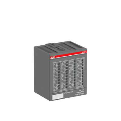
The controller is equipped with comprehensive input and output interfaces, including 8 channels of digital input (DI) and 6 channels of digital output (DO), which can access on-site control signals such as limit switches and emergency stop buttons, and output control signals such as motor start/stop and fault alarms. It provides 4 channels of analog input (4mA~20mA, 0V~10V) and 2 channels of analog output, which can connect to sensor signals such as pressure and liquid level to realize closed-loop control, or output operating parameters to the instrument panel for display. In terms of communication, it has built-in mainstream industrial communication interfaces such as PROFINET, Modbus RTU, and EtherNet/IP, which can be seamlessly connected to controllers such as ABB AC800M, Siemens S7-1500, Rockwell ControlLogix, and upper-level monitoring systems (such as ABB OPC Server and WinCC). Through the communication network, remote parameter configuration, operation status monitoring, and fault information upload can be realized. Controller debugging and maintenance can be completed without on-site operation, greatly improving system integration efficiency. In addition, the controller supports CANopen bus expansion, which can connect multiple auxiliary control modules to realize multi-motor coordinated control.
3. Comprehensive Protection and Fault Diagnosis for Convenient Operation & Maintenance
The controller has built-in multiple protection functions such as overcurrent, overvoltage, undervoltage, overtemperature, motor locked-rotor, phase failure, and ground fault. When an abnormal working condition is detected, it can cut off the power output and trigger protection actions within 1ms to avoid damage to the motor and controller. For example, when the motor is locked-rotor, the controller immediately limits the armature current to a safe range and sends a locked-rotor alarm signal; when the internal temperature of the controller exceeds 60℃, it automatically reduces the output power and starts the cooling fan, and triggers shutdown protection if the temperature continues to rise. In terms of fault diagnosis, the controller has a fault diagnosis coverage rate of 99.5%, which can accurately identify problems such as control module faults, power unit faults, encoder faults, and communication faults, and generate standardized fault codes (e.g., F001 for overcurrent fault, F010 for communication interruption). It uploads fault information through local LED indicators (red fault light, yellow warning light) and the communication network, clearly indicating the fault location and handling suggestions (e.g., "F005: Motor ground fault, please check motor insulation"). At the same time, the controller has a built-in fault recording function that can store the latest 100 pieces of fault information (including fault type, occurrence time, and operating parameters), providing a basis for operation and maintenance personnel to trace the cause of faults.
4. Redundancy Configuration and Enhanced Design for Stable and Reliable Operation
The controller supports 1:1 hot redundancy configuration. The main and standby controllers realize real-time data synchronization through a dedicated redundant communication link, with synchronized content including control parameters, operation status, and fault information, and a synchronization delay of ≤1ms. During normal operation, the main controller performs control functions, while the standby controller monitors the status of the main controller in real time and synchronizes data; when the main controller encounters abnormal conditions such as communication interruption or module failure, the standby controller can complete disturbance-free switching within 5ms and take over control functions to ensure uninterrupted motor operation. For example, during the operation of a port crane, if the main controller fails suddenly, the standby controller switches seamlessly to avoid the crane's lifted load from falling. In terms of hardware, the controller uses wide-temperature-resistant components (standard version: -10℃~60℃) and an enhanced electromagnetic shielding shell, which can resist electromagnetic interference in industrial sites; it is equipped with an anti-vibration installation structure to adapt to scenarios with large vibrations such as mines and ports. In addition, the controller adopts a modular design, and modules such as the control core board and communication board can be replaced individually, reducing operation and maintenance costs.
5. Flexible Configuration and Parameter Adaptation for Strong Versatility
The controller supports parameter configuration through ABB Drive Composer software. The software has a built-in motor parameter self-learning function. After connecting to the motor, it can automatically identify parameters such as the motor's rated voltage, rated current, armature resistance, and excitation inductance without manual input, simplifying the debugging process. The software provides a wealth of application macros (e.g., rolling mill macro, hoist macro, papermaking machine macro), which preset control parameters for different industry scenarios. After importing the corresponding application macro, configuration can be completed with only fine-tuning, greatly shortening the debugging time. For example, in the paper machine traction control scenario, after importing the "paper machine traction macro", the controller automatically configures key parameters such as speed regulation PID parameters and soft start time to adapt to the control requirements of paper traction. In addition, the controller supports parameter backup and restoration functions, which can save the configured parameters to a USB flash drive. When replacing a new controller, the parameters can be imported directly to avoid repeated debugging.
IV. Working Principle
The ABB AX521 1SAP250100R0001 realizes high-precision control of DC motors through the collaboration of hardware circuits and software algorithms, based on the core workflow of "signal acquisition - control calculation - power output - feedback regulation". The specific working mechanism is as follows:
1. Signal Acquisition and Preprocessing
On-site sensor signals (such as encoder, current sensor, and voltage sensor signals) and control signals (such as start/stop commands and speed setpoint signals) are connected to the controller through input interfaces. The motor speed pulse signal fed back by the encoder is processed by a pulse shaping circuit and then sent to the speed measurement unit to be converted into a real-time speed value; the armature current and excitation current are collected by current sensors, filtered and amplified by a signal conditioning circuit, and then sent to the ADC conversion unit to be converted into digital signals; analog setpoint signals (such as 4mA~20mA speed setpoint) are converted into digital signals by the analog input circuit; digital input signals (such as emergency stop signals) are sent to the digital processing unit after photoelectric isolation. All collected signals undergo photoelectric isolation processing with an isolation voltage of ≥2500Vrms, which effectively blocks external interference signals and ensures the accuracy of signal acquisition.
2. Control Calculation and Strategy Execution
The control core unit performs control calculations based on the configured control mode (speed, torque, current, or voltage closed-loop), setpoint signals, and feedback signals. It adopts a vector control algorithm to decompose the armature current into excitation components and torque components, and calculates the deviation signal (difference between the setpoint value and the feedback value) through a PID regulator to generate control commands for armature voltage and excitation current. For example, in the speed closed-loop control mode, the control core unit compares the set speed with the actual speed fed back by the encoder, calculates the speed deviation, outputs the torque setpoint through the speed PID regulator, and then outputs the armature voltage control signal through the current PID regulator combined with the current feedback signal. During the control calculation process, the controller automatically adjusts the PID parameters according to the motor operation status to ensure the dynamic response performance of the control system. At the same time, the control core unit monitors the motor parameters and operation status in real time and executes control strategies such as soft start, soft stop, and speed limitation.
3. Power Output and Feedback Regulation
The control commands generated by the control core unit are sent to the power drive unit. The power drive unit rectifies the input AC power (AC 220V or AC 380V) into DC power, and then adjusts the voltage and current output to the motor armature and excitation winding through PWM (Pulse Width Modulation) technology to realize the control of motor speed or torque. The PWM modulation frequency can reach 10kHz, ensuring the stability of the output current and reducing the electromagnetic noise during motor operation. At the same time, the power drive unit has built-in current and voltage detection circuits that collect the output armature current and voltage signals in real time and feed them back to the control core unit to form closed-loop regulation. For example, when the armature current increases due to increased motor load, the feedback signal triggers the control core unit to adjust the PWM duty cycle to maintain the current at the set value. In addition, the power drive unit is equipped with a cooling fan and a temperature detection circuit to ensure stable operation under high-load working conditions.
4. Redundancy Switching and Fault Handling
In the redundancy configuration mode, the main and standby controllers synchronize control parameters, operation status, and fault information in real time through a dedicated redundant communication link. The standby controller continuously monitors the communication status and operating parameters of the main controller. When it detects abnormalities such as communication interruption of the main controller, control module failure, or abnormal power output, it immediately triggers the redundancy switching logic and takes over the power output control right within 5ms to ensure no fluctuation in motor operating parameters. In terms of fault handling, the fault diagnosis unit monitors parameters such as input/output signals, power drive unit status, and controller internal temperature in real time. When an abnormality is detected, it immediately generates a fault code, triggers corresponding protection actions (such as cutting off power output and activating the alarm relay), and uploads the fault information through LED indicators and the communication network. Operation and maintenance personnel can view the fault code and handling suggestions through the upper-level monitoring system or local operation panel to quickly complete fault troubleshooting and repair. After the fault is eliminated, the controller supports manual or automatic reset to resume normal operation.