



Home > Electrical & Electronics > Electrical Control System > TRICONEX 4000056-002 Communication Module
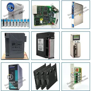
TRICONEX 4000056-002 Communication Module
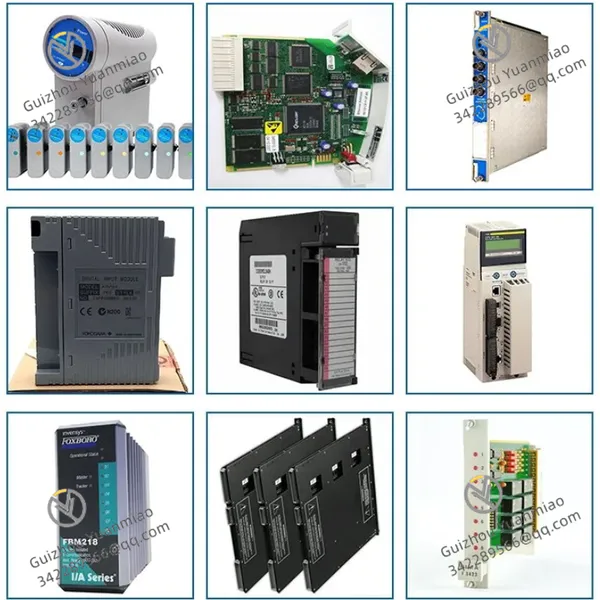
TRICONEX 4000056-002 Communication Module photo-1

Negotiable MOQ: 1 Piece (Price negotiable depending on order volume and customization)
Key Specifications
Get Latest Price
Material:
Other, Global universal model
Condition:
Other, Global universal model
Task:
Other, Global universal model
Payment & Shipping
Payment Methods:
Port of Shipment:
guizhou
Delivery Detail:
Delivery time depends on order quantity.
Material Other, Global universal model
Condition Other, Global universal model
Task Other, Global universal model
Mathematical Model Other, Global universal model
Signal Other, Global universal model
Customized Non-Customized
Structure Other, Global universal model
Operating Temperature -40°C ~ 70°C
Relative Humidity 5%~95% (non-condensing)
Dimensions 100mm×160mm×30mm

I. Overview


TRICONEX 4000056-002 is a dedicated communication module for Triple Modular Redundant (TMR) Safety Instrumented Systems (SIS). Its core positioning is a "safety-level data interaction hub - redundant communication link carrier - multi-protocol conversion interface". It is mainly used to realize bidirectional data transmission between the internal components of the TRICON system (CPU modules, I/O modules) and external devices (such as operator station HMIs, third-party PLCs, and SCADA systems). Meanwhile, it ensures the security and continuity of data transmission through the TMR communication architecture, providing reliable communication support for safety-related scenarios such as Emergency Shutdown Systems (ESD) and unit protection systems.


It has three core advantages:
  1. Triple modular redundant communication: Independent three communication channels are used to implement "2-out-of-3" (2oo3) voting logic, avoiding data interruption caused by single-point communication failures;

  2. Multi-protocol compatibility: It integrates multiple types of communication interfaces such as Ethernet, Modbus, and TRICON dedicated bus, supporting data interaction across devices and systems;

  3. Safety-level fault isolation: Equipped with a hardware-level communication fault detection circuit, it can real-time monitor abnormalities such as link interruption and data packet loss, ensuring that communication faults do not spread to the safety control logic. With a Mean Time Between Failures (MTBF) of more than 2 million hours, it is a core component for internal and external data interaction in the TRICON system.


II. Technical Parameters


  1. Basic Specifications


Item Parameter Details
Equipment Type Safety-level Communication Module for TRICON System
Compatible Systems


TRICONEX TRICON Triple Modular Redundant Safety Instrumented Systems (e.g., TRICON CX, TS3000 Series)


Functional Safety Level


Compliant with IEC 61508 standard, supporting SIL 3 level (under TMR architecture)


Installation Method


Standard rack slot installation for TRICON (occupies 1 standard module slot)

Overall Dimensions


Standard size for TRICON modules (approximately 100mm×160mm×30mm, suitable for compact rack layout)


Protection Class


IP20 (Installed in the rack, protected against intrusion of solid foreign objects)


Operating Temperature Range

-40°C ~ 70°C (operation); -55°C ~ 85°C (storage)


Power Supply Requirement


Unified power supply from TRICON rack (+5V DC, rated current 1.2A)


2. Performance Parameters


Communication Interface and Protocol Characteristics

Interface Type Specification Parameters Supported Protocols Function Purpose
Ethernet Interface 2 x 10/100Base-TX RJ45 interfaces (redundant configuration) TCP/IP, Modbus TCP, TRICON Dedicated Ethernet Protocol Connects to HMI and SCADA systems to realize remote monitoring and data upload; supports dual-network redundancy to avoid link interruption


Serial Communication Interface

2 x RS485 interfaces (half-duplex, maximum baud rate 115200bps) Modbus RTU (Master/Slave mode), ASCII Protocol Connects to third-party PLCs and intelligent instruments (e.g., flowmeters, pressure transmitters) to collect on-site equipment data


TRICON Backplane Interface

1 x dedicated backplane bus interface (rate 10Mbps) TRICON TMR Redundant Bus Protocol Communicates with CPU modules and I/O modules in the system to transmit collected data and control commands


Expansion Interface


1 x optical fiber interface (optional, supporting single-mode/multi-mode)

Optical Fiber Ethernet Protocol Long-distance communication (maximum 2km for multi-mode / 20km for single-mode), suitable for system connection across workshops and regions


Redundancy and Safety Characteristics

  • Redundant Architecture: Integrates TMR communication processing channels. Each data stream is processed by three independent communication controllers, and valid data is output through "2oo3" voting. A single-channel fault (e.g., damage to one Ethernet controller) does not affect overall communication;

  • Fault Diagnosis Coverage: ≥99.5%, capable of detecting 10 types of faults such as "Ethernet link interruption", "RS485 communication timeout", "data verification error", and "backplane bus fault", with a diagnostic response time ≤50ms;

  • Secure Communication Mechanism: Supports encrypted data transmission (optional TLS 1.2 protocol) and message CRC verification (32-bit cyclic redundancy check) to prevent data tampering or packet loss. When a severe fault is detected (e.g., two communication channels fail), it automatically triggers a "communication fault alarm" and maintains the output of the last valid data, avoiding misoperation of downstream systems due to data loss.


Data Transmission Performance

  • Ethernet Transmission Rate: 10/100Mbps auto-negotiation. The maximum data throughput of a single interface is 80Mbps, supporting simultaneous connection of 16 HMI clients or SCADA nodes;

  • Serial Communication Rate: The baud rate of the RS485 interface is configurable (9600bps ~ 115200bps). Each interface supports 32 slave devices (Modbus RTU protocol), with a maximum communication distance of 1200m (using shielded twisted-pair cables);

  • Data Delay: Communication delay within the TRICON system (with CPU modules) ≤1ms; external Ethernet communication delay ≤10ms (within local area network); RS485 communication delay ≤50ms (at 115200bps baud rate).


3. Environmental Adaptability


Item Parameter Requirements
Vibration Resistance Compliant with IEC 60068-2-6 standard, 10-500Hz, acceleration 2g (10min/axis)


Shock Resistance


Compliant with IEC 60068-2-27 standard, acceleration 15g (11ms duration, 3 times per axis for 3 axes)


Humidity Tolerance


5%-95% RH (no condensation, at 25°C ambient temperature)


Electromagnetic Compatibility


Radiation Emission: EN 55022 Class B; Immunity: EN 61000-6-2 (Electrostatic Discharge ±8kV contact/±15kV air, Electrical Fast Transient ±2kV, Surge ±4kV)

微信图片_20250802094916


III. Functional Features


1. Triple Modular Redundant Communication and Safety Assurance

  • TMR Communication Architecture: Each external communication link (e.g., Ethernet, RS485) corresponds to three independent communication processing channels (controller, buffer, verification circuit). During data transmission, "2oo3" voting is executed — when the data received by any two channels is consistent, it is determined as valid data and forwarded to the system. If one channel fails (e.g., link interruption), the remaining two channels can still communicate normally, completely avoiding interruption between the system and external monitoring caused by single-point communication faults, and meeting the "no single-point fault" requirement of the SIL 3 safety level;

  • Fault Isolation and Alarm: Equipped with a built-in communication fault isolation circuit. When an abnormality (e.g., data verification error, link timeout) is detected in one communication channel, the channel is automatically isolated without affecting the operation of other channels. At the same time, fault codes (e.g., F03 = Ethernet 1 link interruption, F12 = RS485 slave timeout) are sent to the HMI via the system bus, and the fault indicator light (red flashing) on the front of the module is triggered to remind maintenance personnel to handle it in a timely manner;

  • Secure Data Transmission: Supports message encryption (optional TLS 1.2) and identity authentication for the Modbus TCP protocol to prevent illegal access to the communication network by external devices. All data transmissions adopt 32-bit CRC verification to ensure data integrity (verification error rate


2. Multi-Protocol Compatibility and Cross-System Interaction

  • Full-Scenario Communication Coverage:

    • With upper-layer monitoring systems: Connects to SCADA systems (e.g., Intouch, WinCC) and operator station HMIs via the Ethernet interface (Modbus TCP protocol) to realize real-time data upload (e.g., process parameters, equipment status) and control command issuance (e.g., manual reset, parameter modification);

    • With third-party devices: Connects to intelligent instruments, PLCs (e.g., Siemens S7-300), and frequency converters via the RS485 interface (Modbus RTU protocol) to collect non-safety-related auxiliary data (e.g., pump temperature, valve opening), avoiding direct coupling between safety systems and non-safety devices;

    • Internal system collaboration: Communicates with CPU modules and I/O modules at high speed via the TRICON backplane bus to transmit I/O collected data (e.g., 4-20mA analog signals, digital signals) and safety control commands (e.g., emergency shutdown signals) with a delay ≤1ms;


  • Flexible Protocol Configuration: Communication parameters (such as Ethernet IP address, RS485 baud rate/parity bit, Modbus slave address, and data collection cycle (configurable from 100ms to 10s)) can be customized via the TRICON system configuration software (TriStation 1131). No hardware jumpers are required, adapting to the communication needs of different on-site devices;

  • Optical Fiber Expansion Capability: An optional optical fiber interface module is available, supporting single-mode/multi-mode optical fiber communication with a maximum transmission distance of 20km (single-mode). It is suitable for long-distance communication across workshops and regions (e.g., system connection of distributed devices in petrochemical plants). Moreover, optical fibers have strong anti-electromagnetic interference capabilities, avoiding the impact of strong electromagnetic environments (e.g., frequency converters, high-voltage motors) in industrial sites on communication.


3. Industrial-Grade Reliability and Environmental Adaptation

  • Wide-Temperature and Harsh Environment Tolerance: The operating temperature range of -40°C ~ 70°C covers outdoor cabinets in cold regions (e.g., wellhead control cabinets in northern oilfields) and areas near high-temperature equipment (e.g., beside heating furnaces in refining units), without the need for additional temperature control equipment. The PCB adopts a conformal coating (moisture-proof, corrosion-proof, dust-proof), extending the service life to more than 12 years in high-humidity and oil-gas-rich environments of petrochemical workshops;

  • Enhanced Anti-Interference Design: The power input end is equipped with an EMI filter (compliant with EN 55022 Class B radiation standard), the communication interface adopts photoelectric isolation (isolation voltage 2500V AC for 1 minute), and the Ethernet interface supports electromagnetic compatibility optimization in accordance with the IEEE 802.3 standard. It can resist ±4kV surges and ±2kV electrical fast transients, ensuring stable operation of the communication link in strong electromagnetic environments (e.g., near rolling mills in steel plants);

  • Durable Material Selection: Uses long-life industrial-grade communication chips (service life ≥ 80,000 hours @ 40°C), gold-plated connectors (plugging/unplugging times ≥ 1,000), and the module housing is made of flame-retardant ABS material (UL94 V-0 grade), meeting the requirements of industrial fire protection and mechanical stability. It can withstand cabinet vibration (10-500Hz, acceleration 2g) without affecting communication performance.


4. Convenient Operation, Maintenance and Status Monitoring

  • Visual Status Indication: The front panel is equipped with 8 LED indicators, including "Power Light (yellow steady on = normal power supply)", "Ethernet 1/2 Status Lights (green flashing = normal communication)", "RS485 1/2 Status Lights (blue flashing = normal communication)", "Redundancy Status Light (white steady on = normal TMR)", and "Fault Light (red flashing = communication fault)". The operating status of each communication link can be quickly determined without accessing the system software (e.g., if the Ethernet 1 light is off, it indicates that the link is interrupted);

  • Remote Diagnosis and Configuration: The TriStation 1131 software allows remote viewing of communication status (e.g., number of Ethernet connections, RS485 slave response rate, data transmission rate) and fault logs (including fault type, occurrence time, and affected link), and supports remote modification of communication parameters (e.g., reconfiguring IP address, adjusting Modbus collection cycle). No on-site module disassembly is required, reducing maintenance workload;

  • Spare Part Compatibility: It is compatible with other communication modules in the TRICON series (e.g., 4000056-001), with consistent module size, interface definition, and communication protocol, enabling direct replacement and reducing the cost of spare part inventory. Meanwhile, it supports module hot-swapping (for some TRICON rack models), allowing replacement without power-off and avoiding system shutdown.


IV. Operation, Maintenance and Troubleshooting


Daily Maintenance Points

  • Status Monitoring: Check the operating status of the communication module via the TRICON HMI daily to ensure the number of Ethernet connections is normal (no abnormal disconnection), the RS485 slave response rate is ≥99%, and there are no communication fault alarms. Check the module's indicator lights on-site to ensure the power light and redundancy status light are steady on, and the indicator lights of each communication interface are flashing normally (no extinction or red flashing);

  • Link Inspection: Inspect the wiring of Ethernet cables and RS485 cables (especially the tightness of terminals) monthly, and re-tighten the screws (torque 0.5-0.8N・m) to avoid loose wiring caused by vibration (increased contact resistance leading to communication packet loss). Check the cleanliness of the optical fiber interface (if available), and wipe the optical port with a dedicated optical fiber cleaning paper to avoid optical signal attenuation caused by dust;

  • Performance Testing: Perform "communication link testing" via the system software quarterly — such as Ethernet ping test (to check connectivity with the HMI, packet loss rate should be

  • Environmental Control: Ensure the temperature inside the cabinet is within the range of -40°C ~ 70°C. Regularly clean the dust from the module's heat dissipation holes (blow along the heat dissipation direction with compressed air) to avoid derated operation of communication chips due to overheating. Check the cabinet's sealing to prevent oil, gas, and dust from entering the module and affecting the performance of communication interfaces.


Common Faults and Solutions


Fault Phenomenon Possible Causes Solutions
Ethernet interface light off (no communication) 1. Loose or faulty network cable; 2. Faulty switch port; 3. Damaged Ethernet controller of the module
  1. Replace with a test network cable, re-plug the RJ45 interface, and use a network cable tester to check the continuity of the cable; 2. Switch the network cable to a spare switch port. If communication is restored, the original port is faulty, and the switch port should be replaced; 3. If the above operations are ineffective, replace the module (damage to the Ethernet controller is mostly irreversible)


RS485 slave no response (reporting "timeout fault") 1. Open/short circuit of RS485 cable; 2. Incorrect slave address configuration; 3. Mismatched baud rate/parity bit
  1. Use a multimeter in continuity mode to test the RS485 cable (A/B lines), locate open or short circuit points, and replace the faulty cable; 2. Verify the slave device address with the system configuration software (e.g., Modbus slave addresses should be consistent); 3. Confirm that the RS485 interface baud rate (e.g., 9600bps) and parity bit (e.g., no parity) match the slave device, and reconfigure the parameters


Communication data packet loss (HMI displays "data refresh interruption") 1. Electromagnetic interference (e.g., close to frequency converters); 2. Excessively long communication distance (RS485 over 1200m); 3. Excessively high bus load (more than 32 slaves)
  1. Check the installation distance between the module and the interference source (should be ≥3m), install ferrite cores on the communication cable, or replace it with a shielded twisted-pair cable (grounding resistance ≤4Ω); 2. If the RS485 communication distance exceeds 1200m, install an RS485 repeater (e.g., Siemens RS485 repeater); 3. Reduce the number of RS485 slaves (≤32) or split the bus into multiple branches


Redundancy status light off (reporting "TMR fault") 1. Poor contact between the module and the rack backplane; 2. Fault in one communication channel; 3. System configuration error
  1. Pull out the module and reinsert it into the rack slot to ensure the contacts are clean and free of oxidation (wipe the contacts with alcohol cotton); 2. Check the faulty channel (e.g., Channel 2 fault) via the system software and replace the module; 3. Verify the TMR configuration of the communication module in the system configuration (e.g., the voting logic should be "2oo3") and re-download the configuration


Data verification error (reporting "CRC error") 1. Poor cable contact (signal attenuation); 2. Power voltage fluctuation (+5V 1. Re-tighten the communication cable terminals, measure the signal amplitude with an oscilloscope (RS485 signal should
Product Tags: 4000056-002

Send Inquiry to This Supplier

* Message
0/5000

Want the best price? Post an RFQ now!
Verified Business License
Business Type
Trading Company
Year Established
2014
Factory Size
1,000-3,000 square meters
Product Certifications
SA8000

