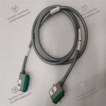
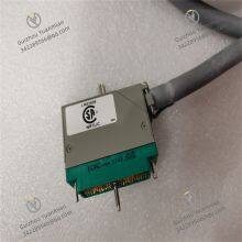
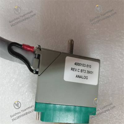
Material
Other, Global universal model
Condition
Other, Global universal model
Task
Other, Global universal model
Mathematical Model
Other, Global universal model
Signal
Other, Global universal model
Customized
Non-Customized
Structure
Other, Global universal model
Operating Temperature
-40°C ~ 70°C
Relative Humidity
5%~95% (non-condensing)
Dimensions
100mm×160mm×30mm
I. Overview
TRICONEX 4000093-310 is a dedicated digital output (DO) module for Triple Modular Redundant (TMR) Safety Instrumented Systems (SIS). Its core positioning is a "safety-level control command execution unit - redundant output drive carrier - fail-safe cut-off interface". It is mainly used to convert the safety control logic of the TRICON system (such as emergency shutdown commands, valve opening/closing commands) into discrete signals recognizable by on-site execution equipment (such as relay energization/de-energization, solenoid valve power-on/power-off). Through the TMR architecture, it implements full-process safety control of "three-channel independent drive - 2-out-of-3 (2oo3) voting - fail-safe cut-off", ensuring that the actions of the execution equipment are consistent with system commands and avoiding misoperations or refusal to act caused by single-point faults.
It has three core advantages:
Triple modular redundant output: Each output signal is controlled by three independent drive circuits and voting logic, and the "2oo3" mechanism ensures reliable output status (actions are executed only when any two drives are consistent);
Hardware-level fault self-cutoff: Built-in detection circuits for output short circuits, overloads, and open circuits, which can quickly cut off the output in case of faults to prevent damage to execution equipment or spread of system faults;
Industrial-grade environmental tolerance: Adopting a wide-temperature design and enhanced anti-interference capability, it is suitable for high-temperature and strong electromagnetic interference scenarios such as petrochemical and chemical industries. With a Mean Time Between Failures (MTBF) of more than 2 million hours, it is a core component for control command execution in safety instrumented systems.

II. Technical Parameters
1. Basic Specifications
2. Performance Parameters
Output Drive Characteristics
Redundancy and Safety Characteristics
TMR Redundant Architecture: Each output channel corresponds to three independent drive circuits (transistors/relays), status detection units, and voting logic. System commands are executed only after confirmation by at least two drive circuits. For example, when the system issues a "valve closing" command, at least two of the three drives need to output a "low level" to trigger the action of the valve actuator, avoiding misexecution of commands caused by single-point drive faults;
Fault Diagnosis Capability: Capable of detecting 7 types of faults, including "output short circuit" (transistor output current >1.2A, relay output contact adhesion), "output open circuit" (load disconnected, current<10mA), "drive circuit fault" (transistor/relay damage), and "24V drive power supply undervoltage" (<18V DC). The diagnostic response time is ≤50ms, and fault information is uploaded to the HMI in real time via the system bus;
Safety Cutoff Mechanism: When a severe fault is detected (such as output short circuit, simultaneous failure of two drives), the module automatically cuts off the output of the channel and locks the fault status (manual reset required) to prevent the fault from spreading to other channels or damaging the execution equipment (e.g., solenoid valve burnout caused by short circuit).
Anti-Interference and Isolation Characteristics
Photoelectric Isolation: Each output channel and the internal logic circuit of the module adopt photoelectric isolation (isolation voltage 2500V AC for 1 minute), and the output drive circuit and 24V power supply circuit adopt power isolation (isolation voltage 1500V DC) to prevent external electromagnetic interference or power fluctuations from affecting the system logic;
Electromagnetic Compatibility: Radiation emission complies with EN 55022 Class B standard; Immunity complies with EN 61000-6-2 standard (Electrostatic Discharge ±8kV contact/±15kV air, Electrical Fast Transient ±2kV, Surge ±4kV);
Surge Suppression: Each output terminal has a built-in TVS transient suppressor (30V DC threshold) to absorb surge voltage induced by on-site cables (such as 2kV transients generated by motor start-stop) and protect the drive circuit.

III. Functional Features
1. Safety-Level Redundant Output and Voting Control
Triple Modular Drive and 2oo3 Voting: Each output command is processed by three logic units of the TRICON system respectively, and then drives the corresponding three independent drive circuits (such as transistors) in the module. The final output is confirmed by the voting logic only when the output status of at least two drive circuits is consistent. For example, when the system issues a "warning light on" command (24V power-on), two transistors need to be turned on to output a "high level" to trigger the action of the warning light. This completely avoids false lighting or non-lighting caused by single-point drive faults (such as damage to one transistor) and meets the "no single-point fault" requirement of SIL 3;
Independent Channel Configuration and Load Adaptation: The 8 channels can be individually configured as "relay output" or "transistor output" via TriStation 1131 software. Relay output is suitable for high-voltage/high-current loads (such as 220V AC warning lights, contactor coils), and transistor output is suitable for low-voltage/low-current loads (such as 24V DC solenoid valves, small relays). It can adapt to different types of on-site execution equipment without replacing the module, reducing the complexity of model selection;
Fault Locking and Manual Reset: When a fault (such as output short circuit) is detected in a channel, the module automatically cuts off the output of the channel and locks the fault status (fault light stays red). Even if the system command returns to normal, the faulty channel can only be re-enabled through manual reset via the HMI or on-site, preventing misoperation of the equipment when the fault is not eliminated (such as module burnout caused by re-powering when the short circuit is not repaired).
2. Intelligent Fault Diagnosis and Safety Protection
Comprehensive Fault Detection and Alarm: Built-in hardware-level fault detection circuit, which real-time monitors the following abnormalities: ① Output short circuit (transistor output current >1.2A, relay contact short circuit); ② Output open circuit (load disconnected, current<10mA); ③ Drive circuit fault (transistor breakdown, relay coil burnout); ④ 24V drive power supply undervoltage (<18V DC). Upon detecting a fault, the channel fault light (stays red) is triggered within 50ms, and fault codes (such as F02 = Channel 2 short circuit, F15 = 24V power supply abnormality) are sent to the HMI via the system bus, facilitating maintenance personnel to quickly locate the fault point (such as determining whether the warning light not turning on is due to a module fault or a load fault);
Distinction Between Self-Recoverable and Non-Recoverable Faults: For recoverable faults such as "transient overcurrent" (e.g., motor start-up inrush current), the self-resetting fuse of the transistor channel automatically resets after the fault is eliminated, without manual intervention. For non-recoverable faults such as "drive circuit burnout" and "relay contact adhesion", the module locks the fault status and prompts "channel/module replacement required" to avoid fault expansion;
Load Protection and Current Limiting Design: The 1.2A self-resetting fuse of the transistor output channel can limit the maximum output current to prevent burnout of the internal circuit of the module caused by load short circuit (such as short circuit of the solenoid valve coil). The relay output contacts are made of silver alloy material, which has arc resistance (can withstand 3A@30V DC breaking current) to avoid output adhesion caused by contact ablation (such as contact faults caused by frequent start-stop of contactors).
3. Industrial-Grade Reliability and Environmental Adaptation
Wide-Temperature and Harsh Environment Tolerance: The operating temperature range of -40°C ~ 70°C covers outdoor cabinets in cold regions (such as control cabinets of natural gas processing stations in northern China) and areas near high-temperature equipment (such as beside reactors in refining units), without the need for additional temperature control equipment. The PCB adopts a conformal coating (moisture-proof, corrosion-proof, dust-proof), extending the service life to more than 12 years in the humid environment (95% RH, no condensation) and oil-gas-rich scenarios of petrochemical workshops;
Enhanced Anti-Interference and Electromagnetic Compatibility: Dual protection of photoelectric isolation for output channels and independent isolation for power supplies can resist electromagnetic interference generated by frequency converters and high-voltage motors in industrial sites (such as no output status fluctuation under ±2kV electrical fast transient interference). The module housing is made of flame-retardant ABS material (UL94 V-0 grade), which self-extinguishes when exposed to fire, meeting industrial fire protection requirements;
Durable Material Selection: Industrial-grade sealed relays (service life ≥1 million operations @ rated load) are used for relays, and automotive-grade MOSFETs (service life ≥80,000 hours @40°C) are used for transistors. The 24V drive power supply circuit has a built-in EMI filter to reduce the impact of power noise on the output. The Mean Time Between Failures (MTBF) is ≥2 million hours.
4. Convenient Operation & Maintenance and Compatibility
Visual Status Indication: The front panel is equipped with 8 channel status lights (green steady on = output "1"/closed, green off = output "0"/open, red steady on = channel fault) + 2 power lights (yellow = +5V logic power supply normal, blue = 24V drive power supply normal) + 1 redundancy status light (white steady on = TMR normal). The status of each channel can be intuitively judged without accessing the system software (e.g., the red steady light of channel 3 indicates a fault in that channel);
Remote Testing and Configuration: "Output testing" (forcing a channel to output "1"/"0" status to verify whether the load action is normal, such as testing whether the solenoid valve can be powered on) and parameter configuration (fail-safe value, channel output type) can be performed remotely via TriStation 1131 software, without on-site module disassembly or load disconnection, reducing maintenance workload (such as testing the action of the emergency shutdown valve without shutting down the system);
Spare Part Compatibility and Hot-Swapping: It is compatible with other digital output modules in the TRICON series (e.g., 4000093-300), with consistent module size, interface definition, and communication protocol, enabling direct replacement and reducing the cost of spare part inventory. Some TRICON racks support module hot-swapping, allowing replacement without power-off and avoiding system shutdown (e.g., under redundant configuration, replacing a faulty module does not affect the operation of other modules).

IV. Operation, Maintenance and Troubleshooting
Daily Maintenance Points
Status Monitoring: Check the module's operating status via the TRICON HMI daily to confirm that the output status of the 8 channels is consistent with system commands (no abnormal "1"/"0" output) and there are no fault alarms. Inspect the module's indicator lights on-site to ensure the power lights and redundancy status light are steady on, and no channel light stays red (fault);
Wiring and Load Inspection: Inspect the wiring between the module's output terminals and load cables (especially critical loads such as emergency shutdown valves and warning lights) monthly, and re-tighten the screws (torque 0.8-1.2N・m) to avoid loose wiring caused by vibration (increased contact resistance leading to output voltage drop, such as 24V output dropping below 18V causing the solenoid valve to fail to act). Measure the load resistance (e.g., the solenoid valve coil resistance should be in the range of 10-100Ω) to check for load open circuits/short circuits;
Output Testing and Fault Simulation: Perform "channel output testing" via the system software quarterly — force key channels to output "1"/"0" status (such as testing the "close" command of the emergency shutdown valve), observe whether the load action is normal, and record the output response time (should be ≤2ms); simulate "transient overcurrent" faults on non-key channels (such as connecting a 0.5Ω test resistor) to verify whether the self-resetting fuse resets normally;
Environmental Control: Ensure the temperature inside the cabinet is within the range of -40°C ~ 70°C. Regularly clean the dust from the module's heat dissipation holes (blow along the heat dissipation direction with compressed air) to avoid derated operation of the drive circuit caused by overheating (such as insufficient transistor output current). Check the cabinet's sealing to prevent oil, gas, and dust from entering the module and affecting the performance of relay contacts or transistors.
Common Faults and Solutions


