

Home > Electrical & Electronics > Electrical Control System > GE IS200ECTBG1ADE Exciter Contact Terminal Board
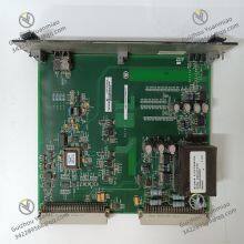
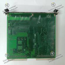
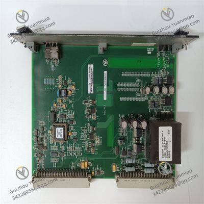
GE IS200ECTBG1ADE Exciter Contact Terminal Board

Negotiable
MOQ: 1 Piece (Price negotiable depending on order volume and customization)
Key Specifications
Get Latest Price
Material:
Other, Global universal model
Condition:
Other, Global universal model
Task:
Other, Global universal model
Payment & Shipping
Payment Methods:
Port of Shipment:
China
Delivery Detail:
Delivery time depends on order quantity.
Related Products
-
 GE IS200EXHSG3REC Relay Driver BoardNegotiableMOQ: 1 Piece
 -
GE DS200TCQCG1AJD RST Overflow BoardNegotiableMOQ: 1 Piece
-
GE IS220YAICS1A L Safety Analog I/O PackNegotiableMOQ: 1 Piece
-
GE ENERGY HYDRAN H201Ci-1 Single-Channel ControllerNegotiableMOQ: 1 Piece
-
GE H201Ti Dissolved Gas Analysis (DGA) MonitorNegotiableMOQ: 1 Piece
Material
Other, Global universal model
Condition
Other, Global universal model
Task
Other, Global universal model
Mathematical Model
Other, Global universal model
Signal
Other, Global universal model
Customized
Non-Customized
Structure
Other, Global universal model
Operating Temperature
-25℃~65℃
Dimensions
100mm×233mm×22mm
Storage Temperature
-40℃~85℃
I. Product Overview
II. Technical Parameters
1. Electrical Parameters
2. Environmental Parameters
3. Physical and Interface Parameters
III. Functional Features
1. Multi-Channel High-Precision Analog Signal Acquisition
2. Multiple Signal Filtering and Anti-Interference
3. Signal Linearization and Calibration
4. Flexible Data Interaction and Status Monitoring

Send Inquiry to This Supplier

* Email
Want the best price?
Post an RFQ now!

1Yr
Business Type
Trading Company
Year Established
2014
Factory Size
1,000-3,000 square meters
Product Certifications
SA8000
You May Also Like
-
GE IS420PUAAH1A Universal Input/Output ModuleNegotiableMOQ: 1 Piece
-
GE IS220UCSAH1AK PAMC Acoustic Monitor ProcessorNegotiableMOQ: 1 Piece
-
GE D20 EME 2400-21004 Substation ControllerNegotiableMOQ: 1 Piece
-
GE D20 EME210BASE-T Ethernet ModuleNegotiableMOQ: 1 Piece
-
GE D20 EME 27-APR-13 Input/Output ModuleNegotiableMOQ: 1 Piece
-
GE WESCOM D200 VME 0517-01230D Versatile And Reliable ModuleNegotiableMOQ: 1 Piece
-
GE WESDAC D20ME 18-MAR-13 Control Output ModuleNegotiableMOQ: 1 Piece
-
GE WES5120 2340-21006 Field Controller Master Unit ModuleNegotiableMOQ: 1 Piece
-
GE WES5120 2340-21004 Field Controller Master Unit ModuleNegotiableMOQ: 1 Piece
-
GE WEA13-13 2508-21001 Substation ControllerNegotiableMOQ: 1 Piece


